UpdateMay 25th: NOTICE: In the pictures of the wiring shown below the wires goes across the PCB both on the upper and lower edge. I later discovered that there was no room in the housing to allow wires to run over the lower edge, so I had to redo some of the wiring. This will be shown in the next update. I didn't update the pictures in this posting, partly as the Hackaday editor is VERY unstable when it comes to replacing/editing the pictures, partly because I think it is nice the logs correctly reflect the actual process ;)
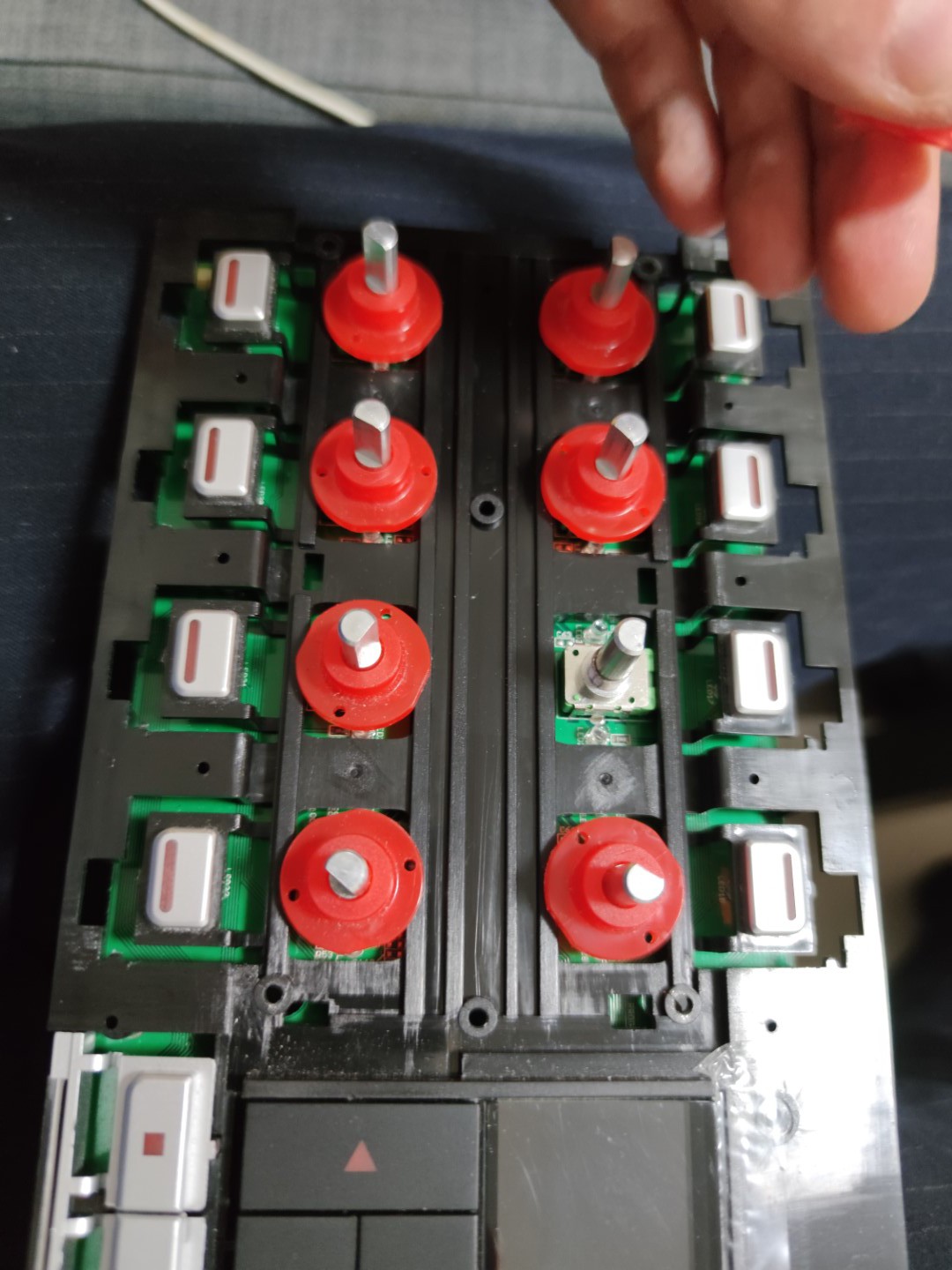
Dismantling the KORE controller was pretty straight forward. Just notice that the red transparent round covers on the potentiometers and rotary encoder are actually threaded on the shafts. So these must be unscrewn to loosen the PCB from the plastic frame.
As there are 8 of the 360 degree eternal rotation potentiometers, each having two outputs, I needed an Arduino board with 16 analog inputs. And the ATmega2560 PRO with onboard CH340G USB to UART bridge is perfect. The ATmega2560 also have enough driving strength on the IO (typ 20mA sink current pr IO / 200mA pr port) to directly drive the onboard LEDs.
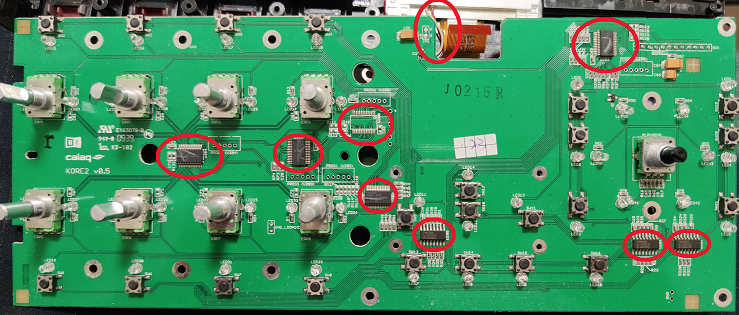
First you have to desolder all the ICs on the PCB. This can be done by applying generous amount of fresh solder over the pins on one side, and make sure to heat all the pins while carefully lifting that side of the IC up from the PCB using a pair of thins tweezers. Secondly do the same for the other side. This will leave a lot of solder residue on the PCB.
Make sure all the ICs are removed. Also cut the wires for the LCD backlight.
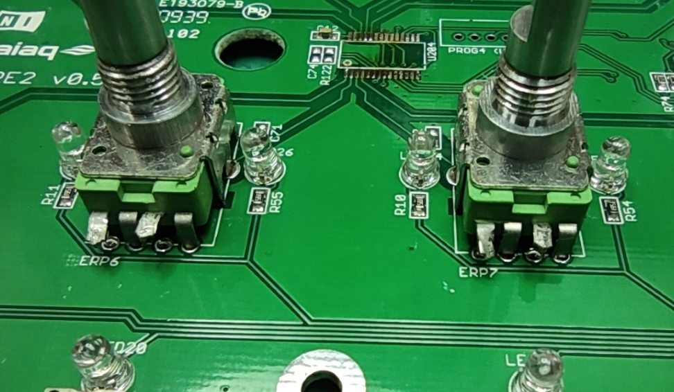
 Use a pair of sharp wire cutters and cut pin 1 and 3 of each of the potentiometers, and bend the pins outwards, and solder wires to the pins, long enough to reach around to the back-side where the Arduino will be mounted.
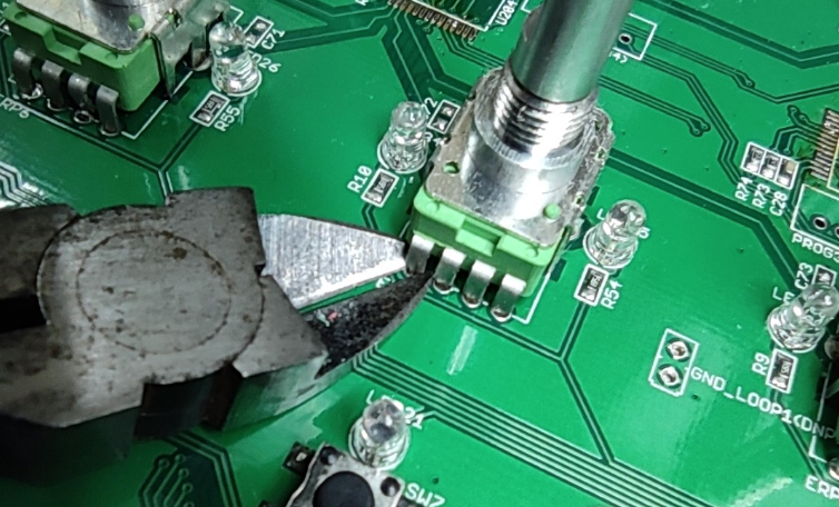
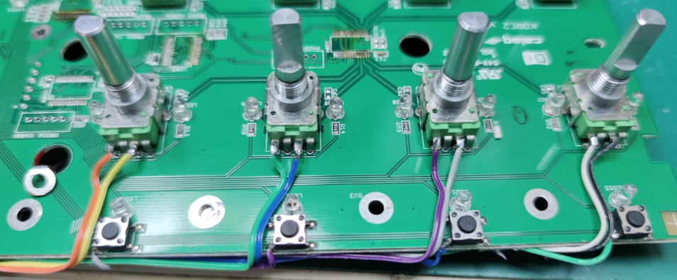 Next, solder wires to the 8 buttons. These buttons are active high, and pulled low by resistors when not activated. Picture below shows which button pin to attach the wire to. If you are unsure, use a multimeter and check with pin goes high when button is pushed
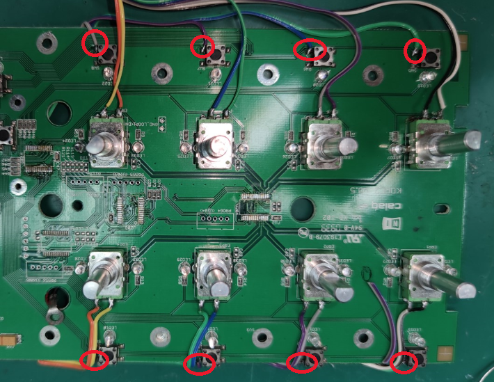
NOTE: As mentioned in the update, this picture shows wires going across both top and bottom of the PCB, but due to space constraints, all wires need to go on top of the PCB. See pictures in later updates.
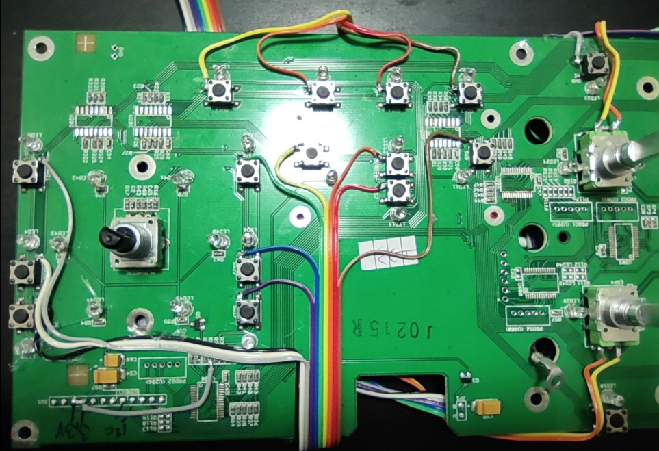
Next solder wires to the other buttons on the PCB
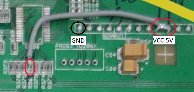
The board originally ruins off 3.3V, but with all the ICs removed it can be powered by 5V, which is desired as this is the IO voltage required by the ATmega2560 Arduino PRO board. The power connection is pins 1 (GND) and 9 + 10 (VCC) on the flat cable connected to the PCB.
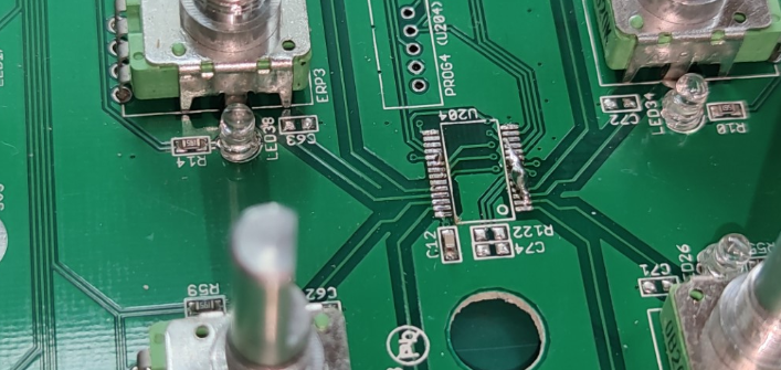
If you power it up you will see the LEDs around the rotary encoder might light up and fade away. This is due to a floating pin on the transistor controlling the LEDs. So Solder a wire between VCC and the top pin of R96. This will ensure the transistor is on and therefore also the LEDs are on. This gives a nice light-effect around the rotary encoder knob.
Discussions
Become a Hackaday.io Member
Create an account to leave a comment. Already have an account? Log In.