 Taylor Schweizer
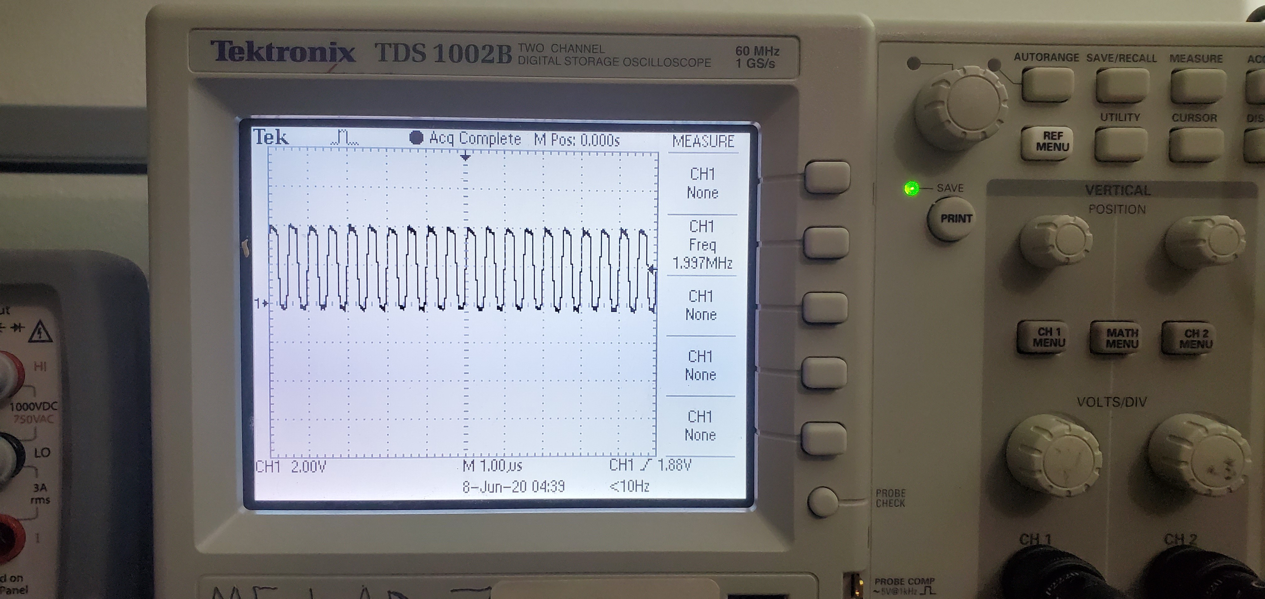
I finally figured out the clock that is running to all of the flip flops! There is a 2MHz clock signal coming from the main CPU board that goes into a 4 bit counter, and the flip flop clock is using the uppermost bit so it is effectively divided by 8. There is also a signal coming from the second bit, so it is the clock divided by 4, going into the 4 input NAND gate. What that means is the flip flops are clocked on a 250 kHz signal.
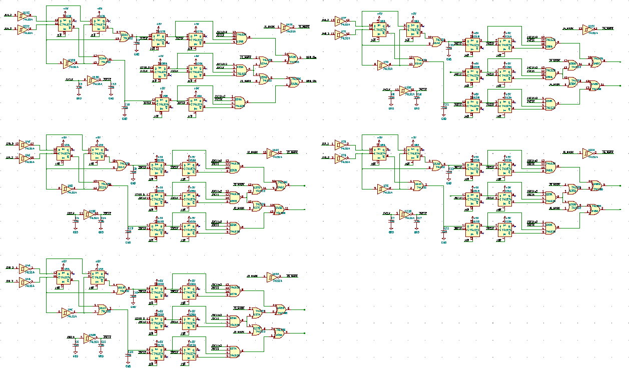
I also finished tracing all of the encoder logic channels. All that remains is the final bits of logic involving multiplexers and stuff.
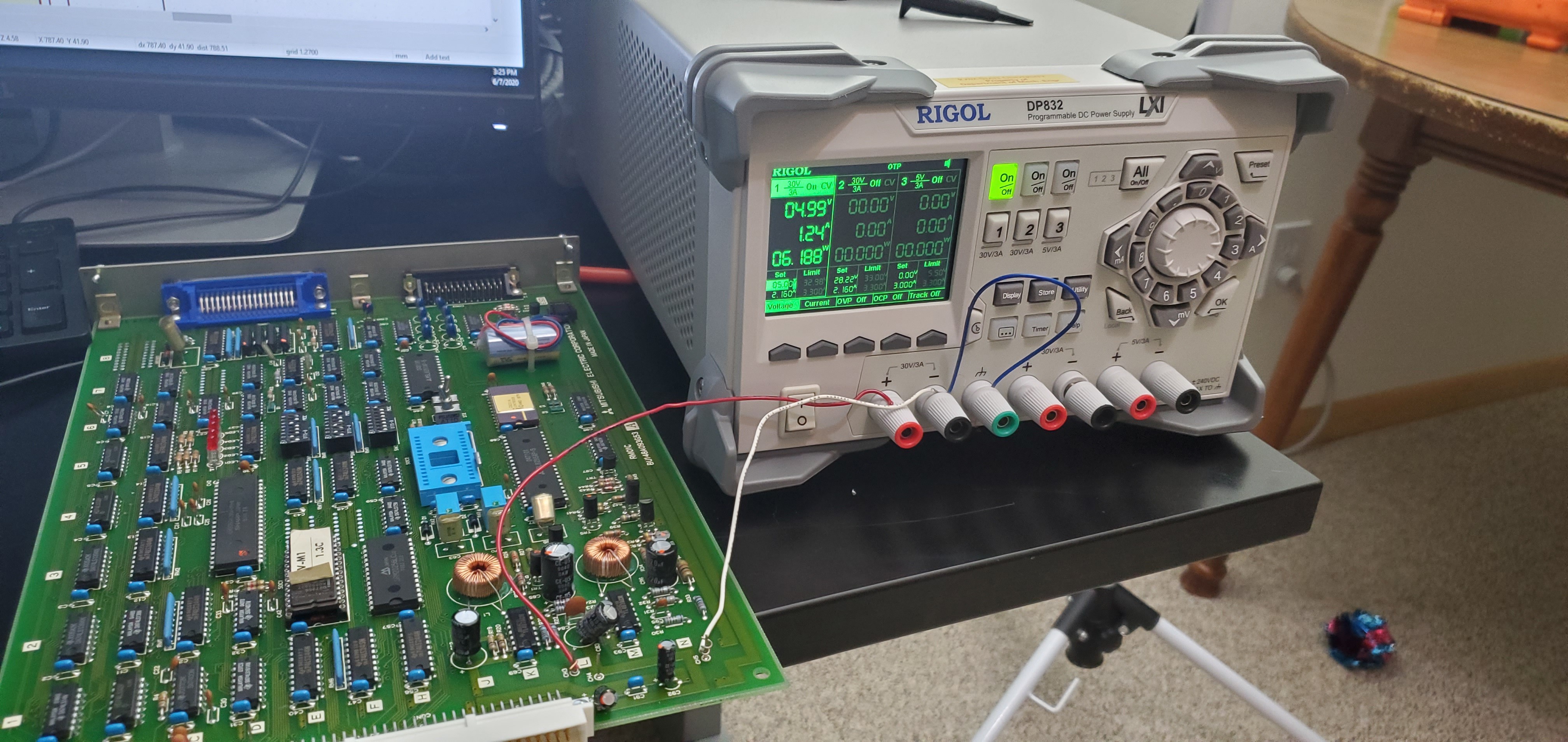
Powering the main CPU board:
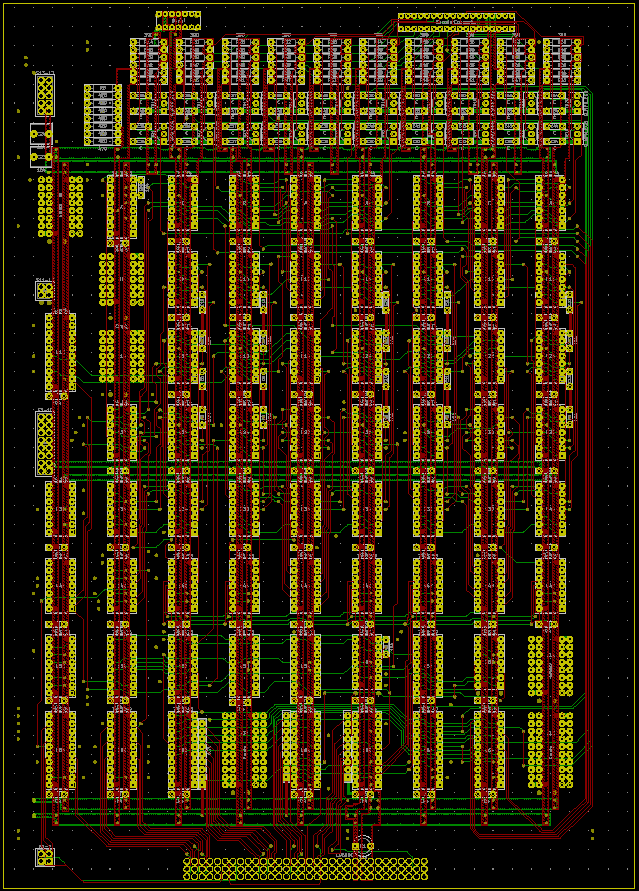
And the schematic/PCB
Discussions
Become a Hackaday.io Member
Create an account to leave a comment. Already have an account? Log In.