 Christian Bjelle
After implementing the video logic in Verilog, and simulated using Icarus Verilog, I decided tro move to hardware.
For this demo, I'll target the MachXO2 breakout board, that has a MachXO2-7000HE, integrated programmer, USB-UART and most of the pins on pads. It does not have footprints for any of the ports I need, so I will put it on a carrier-board made from a failed project PCB.
In my parts bin, there are a couple of Mach XO2 256 and 640 LUT chips, and the design will easily fit in any of those. The 640-part has some block-RAM that can be used as ROM that is lacking in the 256-part, which means I will probably use the 640-part in the final design.
Before putting the MachXO2-BOB on the carrier and doing some modifications I flashed the on-board chip with my design just to verify that I didn't screw something up.
The only way to see if it was alive was to probe with a scope.
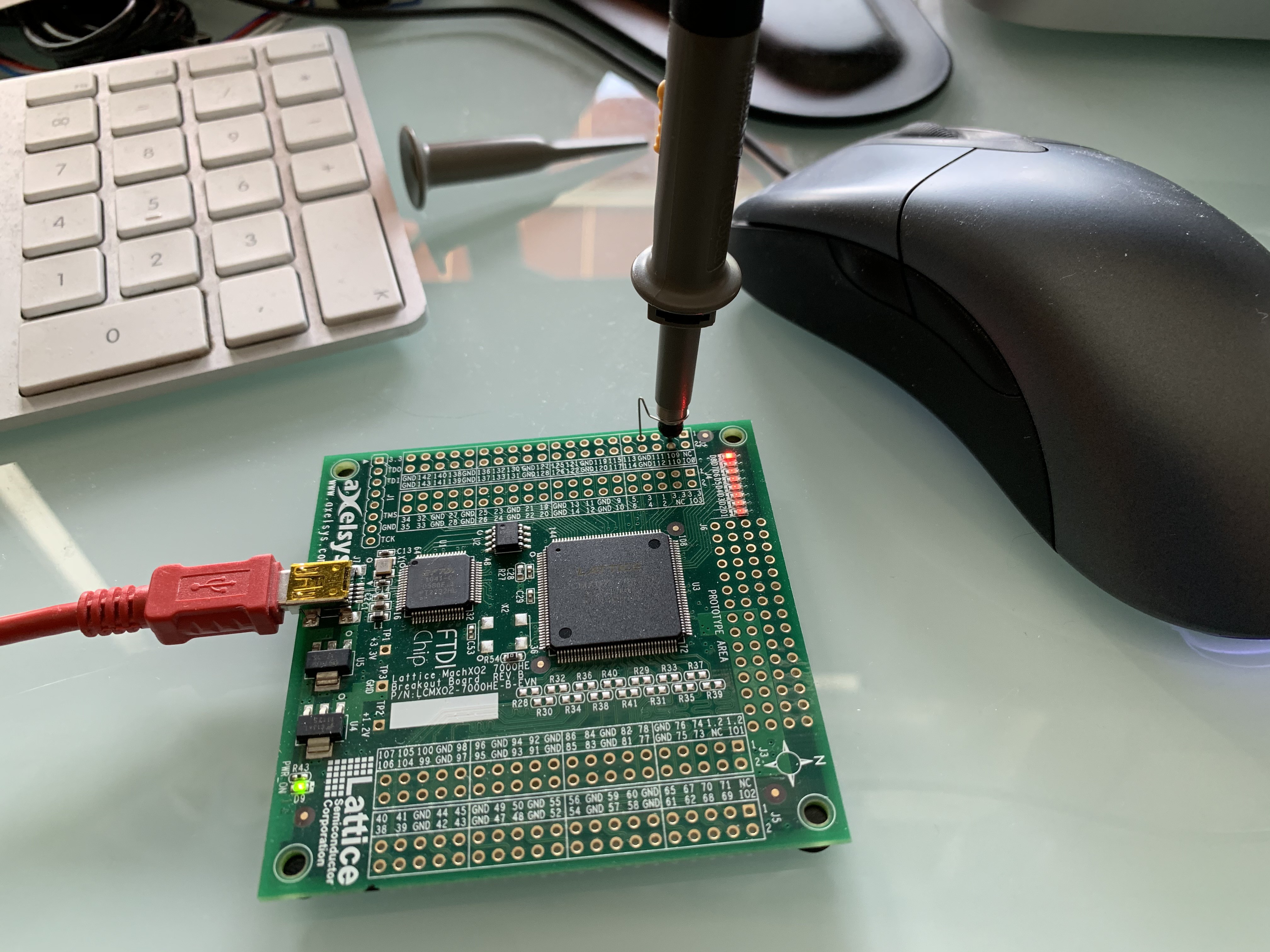
Notice the proper probe-grounding :)
Indeed, there are sync-signals! V-sync is shown in the picture below, and should be exactly 60 Hz, but is a bit off, depending on the internal oscillator of the Mach XO2.
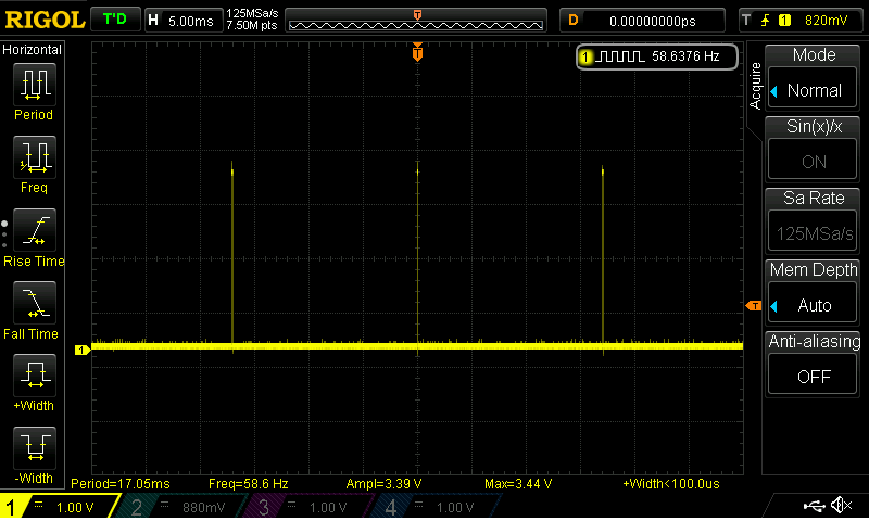
Since the screen is blank after reset, there should be no video signal, but as can be seen in the video below, there is a periodic signal. That signal is the cursor blinking. The Apple I did not have a blinking cursor, but I added one, as one of the very few extensions.
Next up is the carrier board. I need to locate suitable ground- and power-points, as well as the VGA-signal-pads on the board.
Discussions
Become a Hackaday.io Member
Create an account to leave a comment. Already have an account? Log In.