 zst123
This is just a quick post on adding DHT11 wiring to my board and my plan is to connect it to AWS.
In my Android app, I thought it will be good to know the analytics of temperature/humidity of my smart inventory fridge.
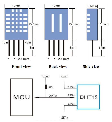
First, let's look at the DHT11 pinout -- it needs 3 wires and a pull up resistor.
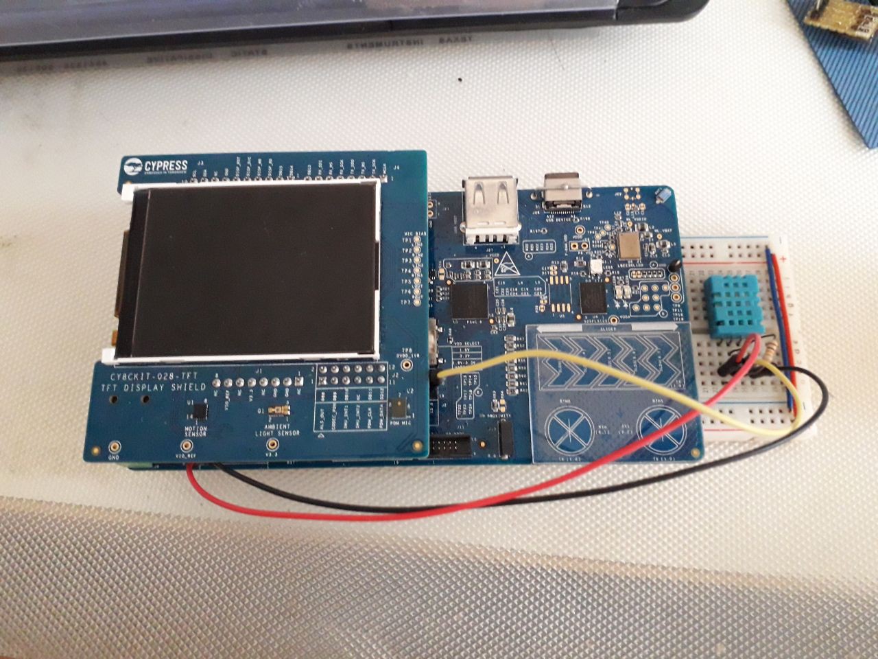
 I wired it on a breadboard as follows.
And then I looked at the PSoC pinout.
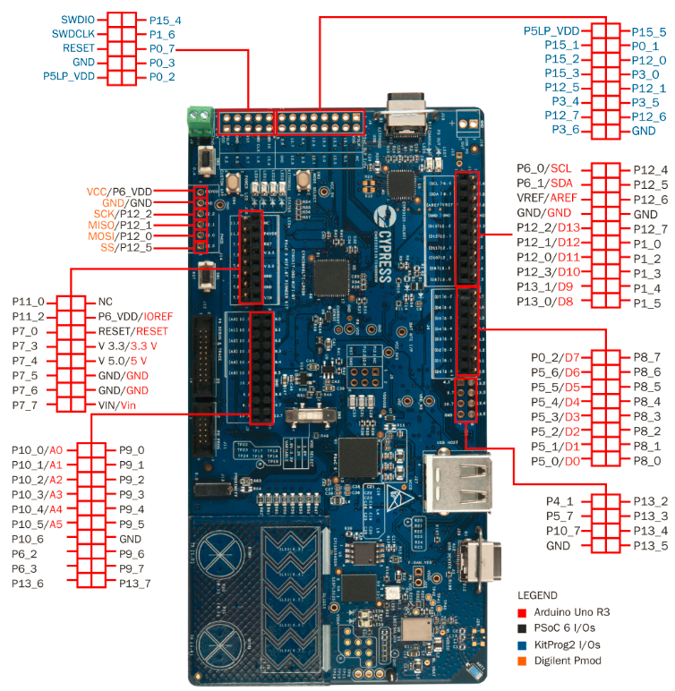
With the LCD in place, I chose the bottom left corner pin, P13_6, which is unused by the LCD. Many other pins are used up by the LCD.
And for VCC and GND, I used the Pmod connector VCC and GND.
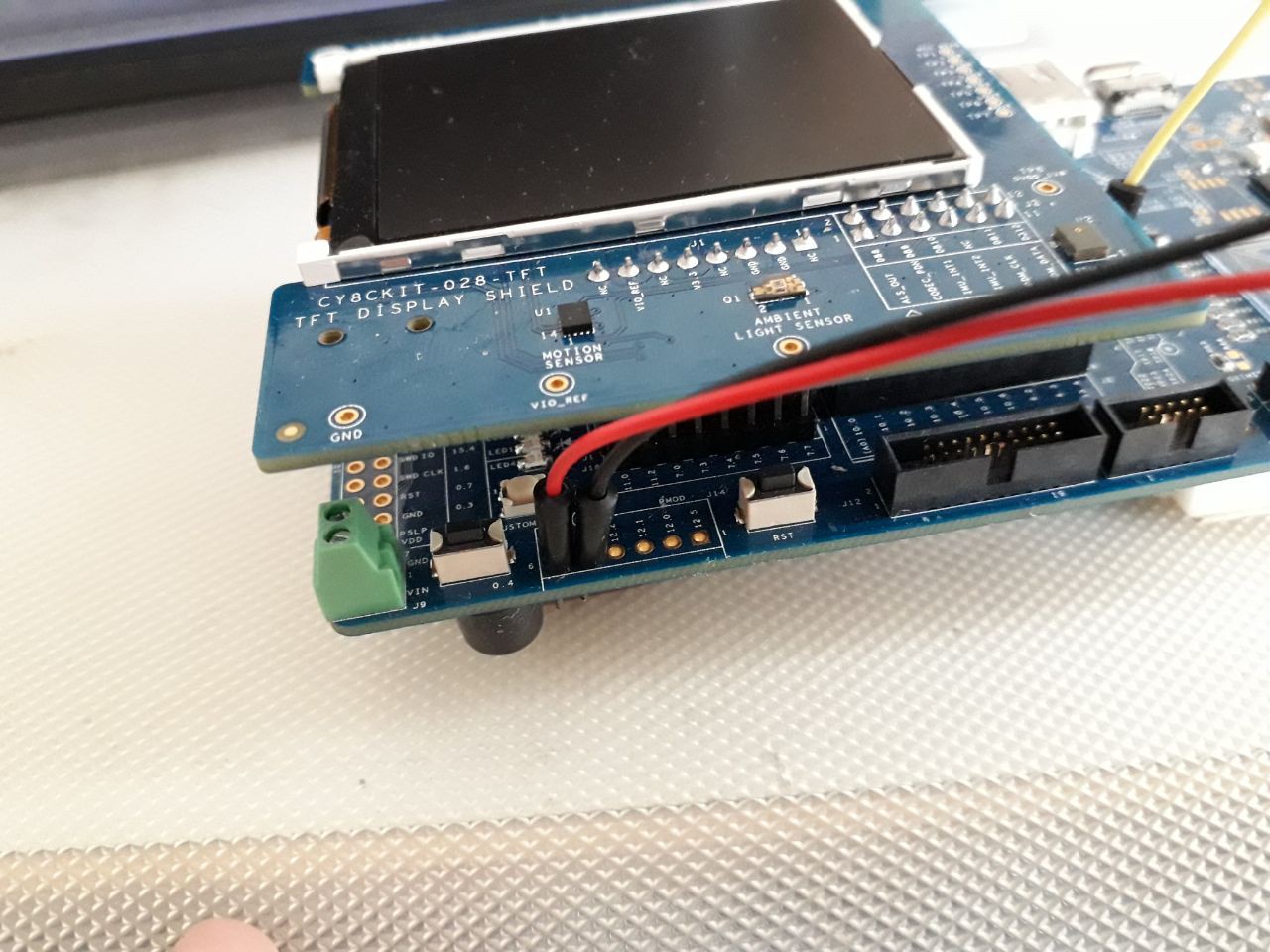
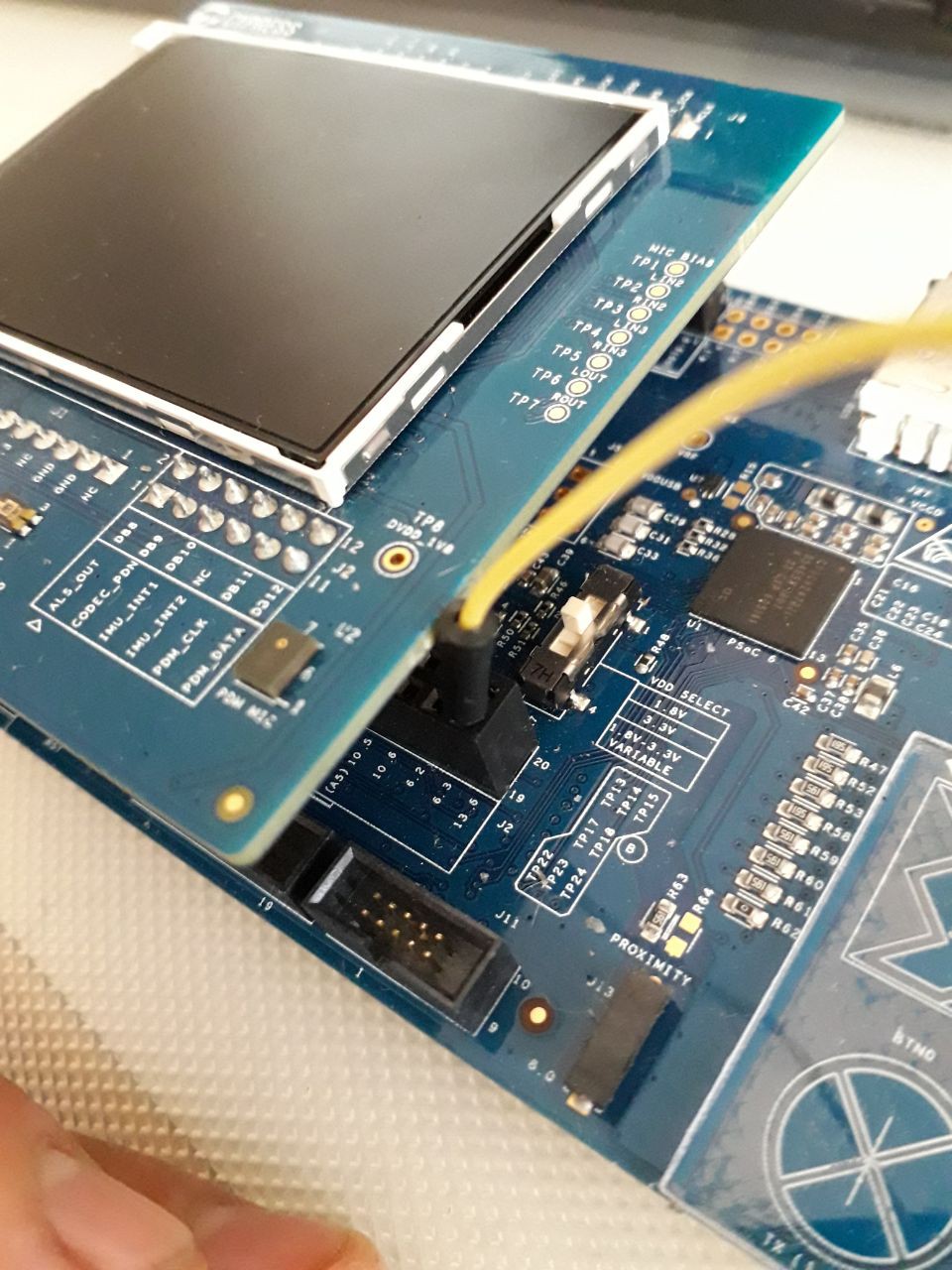
Final pinout.
I will then add the code and upload the data on to AWS.
In my next post, I will finish the basic outline of my Android app.
Discussions
Become a Hackaday.io Member
Create an account to leave a comment. Already have an account? Log In.