 Jasper Sikken
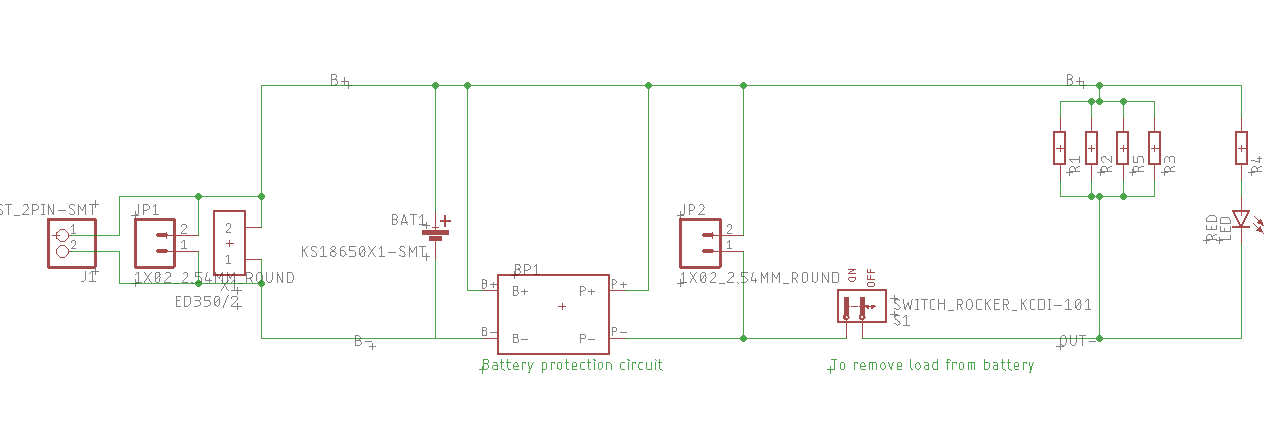
So I have designed a new board and added JP2, which could be used to connect a charger.
I have received the new PCBs and soldered the protection module.
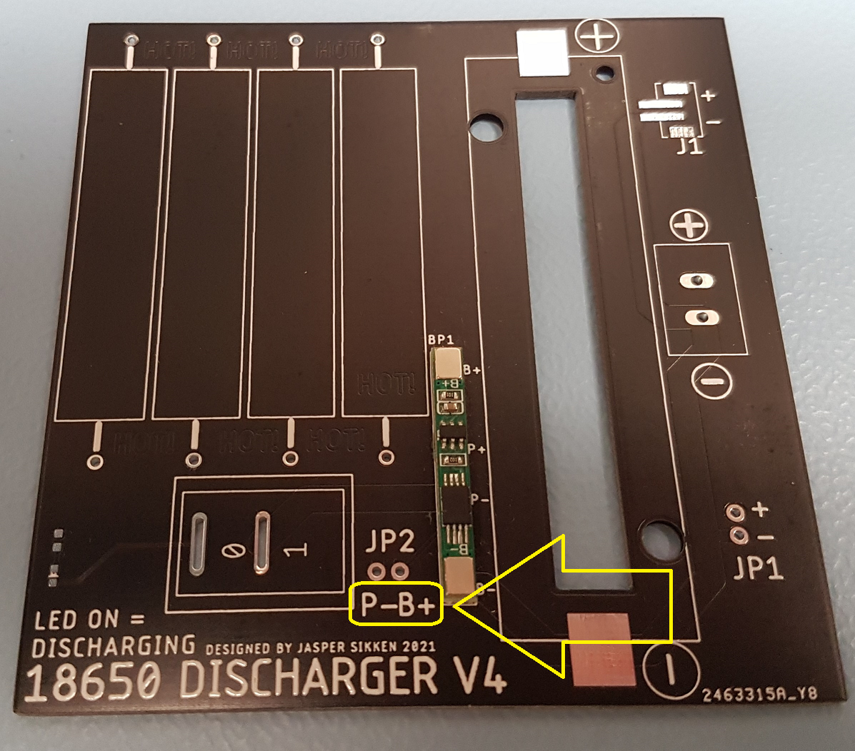
I made a smoll mistake. JP2 is for connecting a battery charger but I accidently swapped the labels P- and B+ in silkscreen.
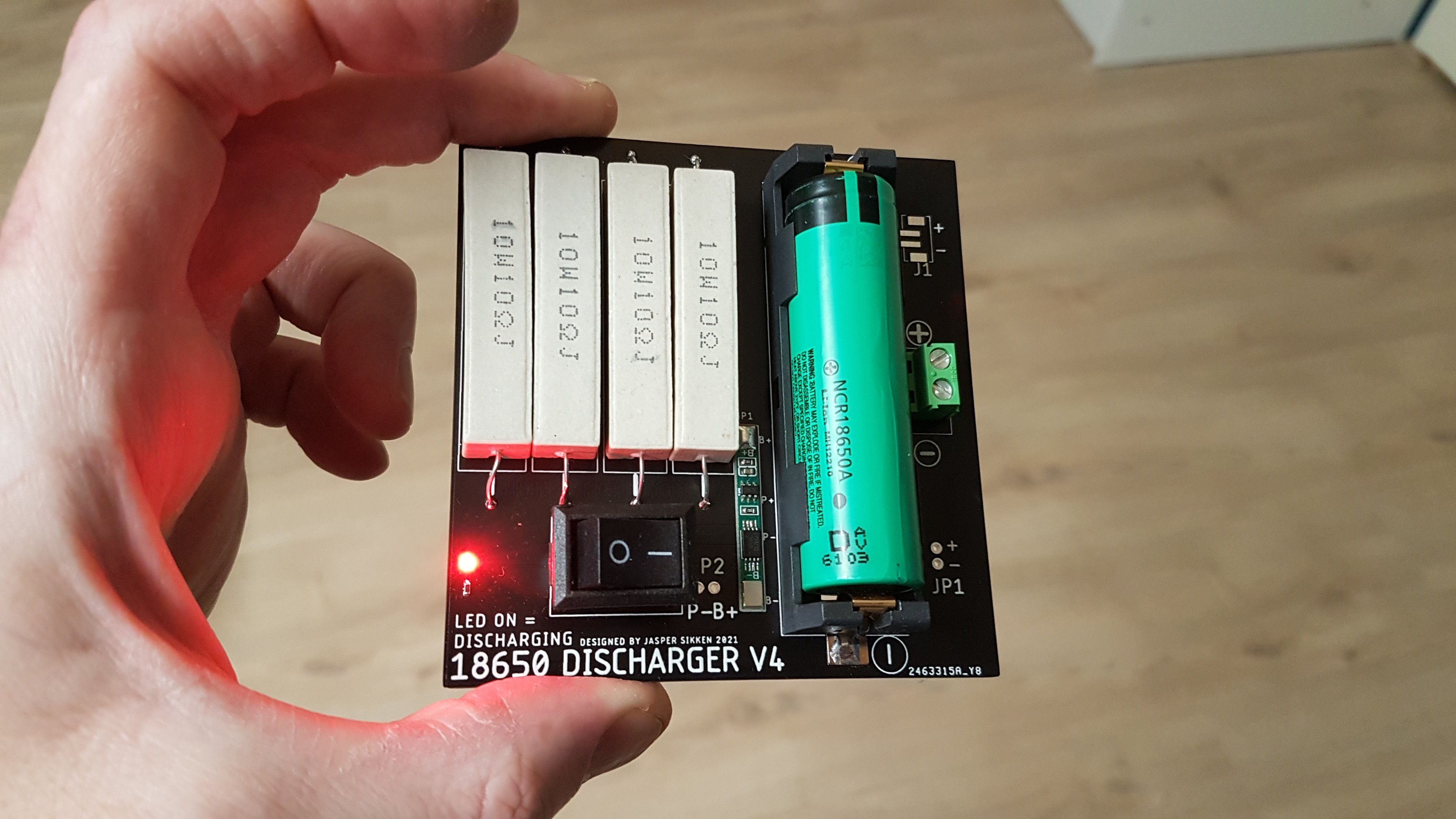
A fully assembled board looks like this
Here's a video
It works great. The 2.5 Ohms load is disconnected at 2.54V and reconnects at 2.87V. The power resistors get hot not dangerously hot, current is about 1.5A which is a safe 0.5C discharge rate for 18650 Li-ion cells. After the battery was discharged to 2.54V the voltage recovered to about 2.85V, which is great. The protection module it self takes about 3uA in normal voltage range and about 0.9uA below 2.54V, which is great. Total BOM cost is 1.70 euro in quantities of 10. I think now it is time to start selling them on Tindie.
Discussions
Become a Hackaday.io Member
Create an account to leave a comment. Already have an account? Log In.