Nick Sayer
The AtmelICE documentation includes the correct pinouts for PDI and AVR-ISP programming interfaces. What they don't tell you (well, they do have a diagram on page 15, but even so, DEAR GOD WHY????), is that the 10 pin 50 mil cable is not a straight-through cable. It's actually got one connector on backwards/upside-down, resulting in a cable that connects pin 1 on the ICE to pin 10 on the other end, 2 to 9 and so on. This wound up costing me dearly, as I ordered a pile of those cables and discovered to my horror that they didn't work.
That really is the trick here. If you have a properly screwed-up cable, then Atmel's pinouts are fairly straightforward.
That leaves target power. Unfortunately, the programmer is set up to use the target voltage to set the voltage levels for the I/O pins used for programming. If there is no target power, then programming won't work (you won't get the green middle light to turn on).
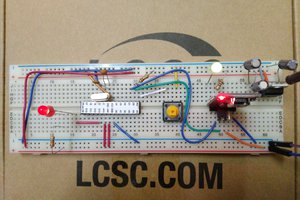
The quick and dirty fix for this is to add a USB-C connector on the board along with a 3.3 volt LDO and a switch to allow selecting between 5 volts (direct from USB) or 3.3 volts (from the LDO).
The PDI, TPI and AVR-ISP pinouts for the AtmelICE are mutually compatible, so the adapter just needs to be wired for AVR-ISP (since it uses all 6 pins and PDI and TPI only use four) and PDI and TPI will work as well.
 Bil Herd
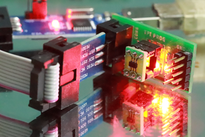
 mit41301
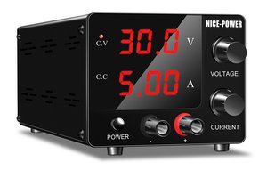
 James Stallings