Materials:
1 PCB: JLCPCB
2 Components: LCSC
3 PCB Design: EasyEDA
Step 1: Notes:
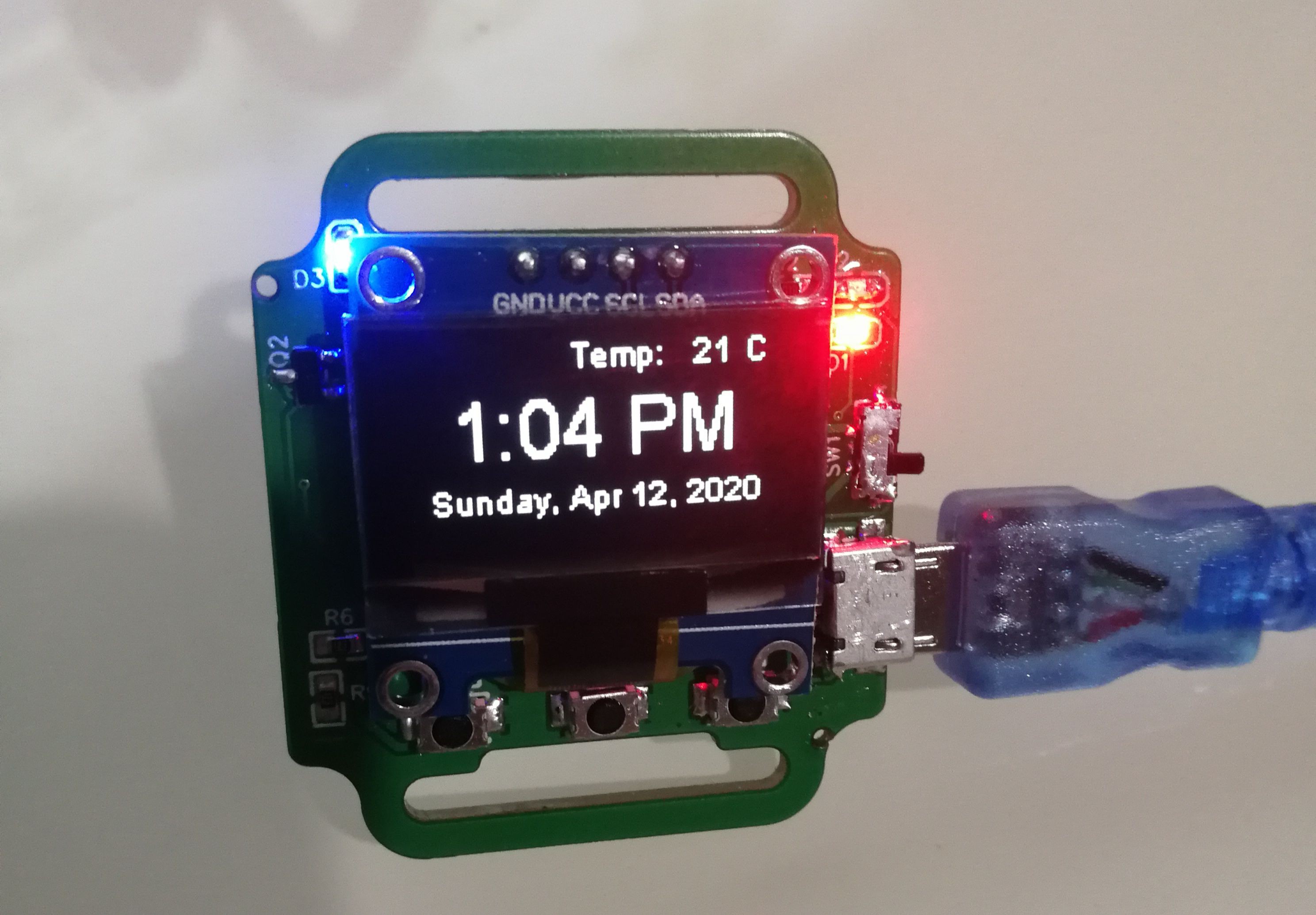
1 The program is compiled using the ARDUINO IDE and some libraries need to be installed.
2 Node MCU 1.0 (ESP-12E Module) should be checked when using the arduino IDE to download the development board.
3 Some of the API calls in the program, are free to apply for their own.
4 Wifi killer cannot be directly used, because IC pin definition is different, need to modify the source code after brushing in, the modified firmware in the engineering annex.
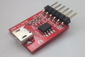
5 USB serial port chip USES CP2102, need to install the corresponding driver.
Step 2: Improvements
1 Energy consumption: ESP8266 has three sleep modes. To use deep sleep, it is necessary to connect GPIO16 to the RESET pin. Esp8266 USES direct power supply, and the LDO can be switched on and off at 3.3v using enable controls.
2 Add a power supply voltage detection circuit.
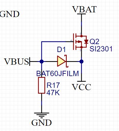
3 Power conversion: the system is powered by USB power when it is connected to USB, and the system is powered by battery when it is removed from USB. PMOS+ Schottky diode scheme is used
Step 3: Schematic
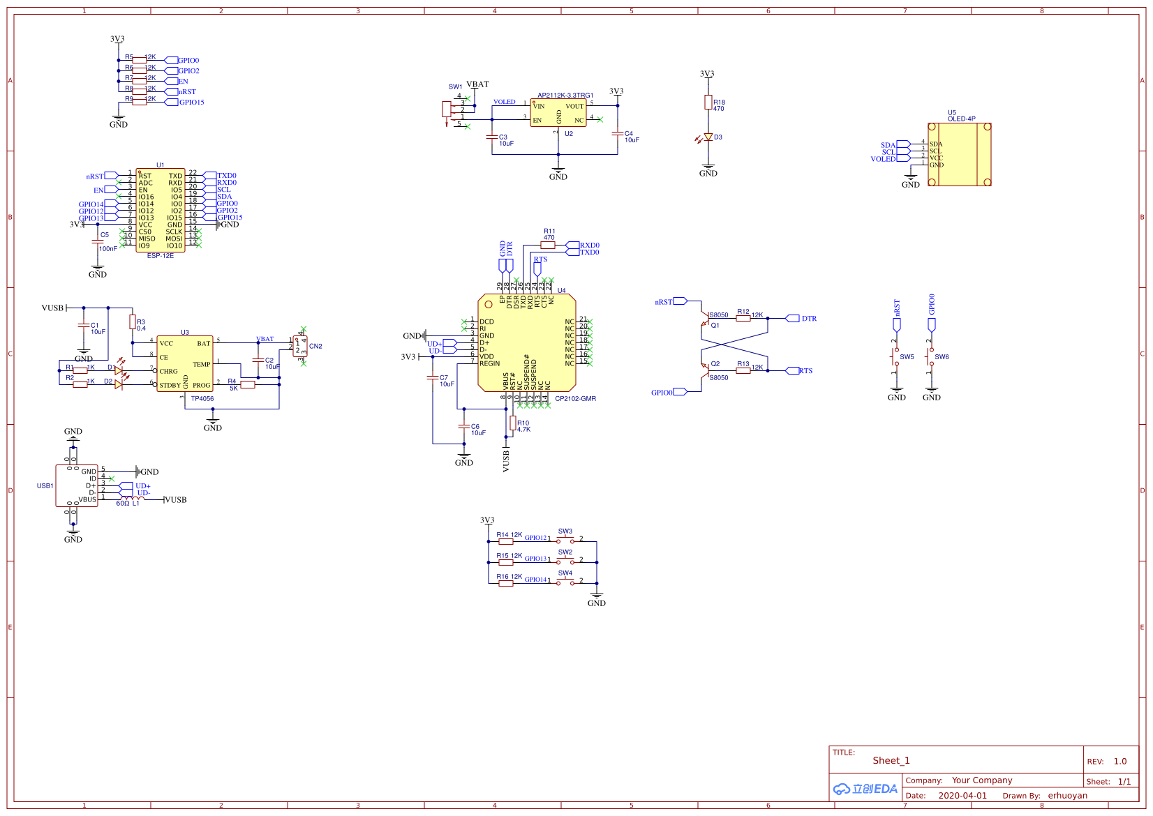
1 According to the need to add peripherals, it will increase the corresponding layout wiring difficulty.
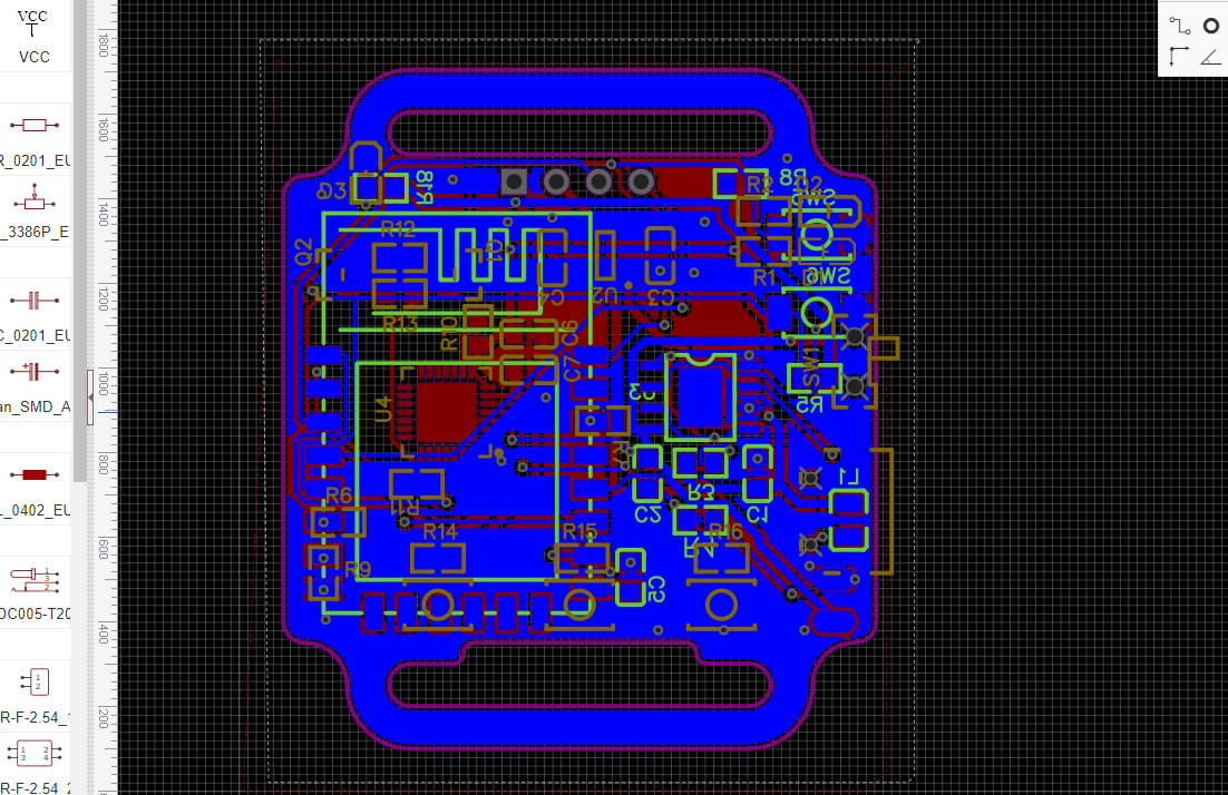
2 According to the official recommendation, the antenna part of the ESP8266 module should stick out of the PCB and not be laid on the floor below, which was not noticed at the time, but no major problems have been encountered so far.
3 Using modules that take up too much space, esp32-pcio-d4 is a highly integrated ESP32 chip that greatly simplifies the design of peripheral circuits by designing a minimal system for ESP32. But wifi killer doesn't seem to support esp32.
Step 4: PCB File
 electronicsworkshops
 ElectroBoy
 Sagar 001
 Lithium ION