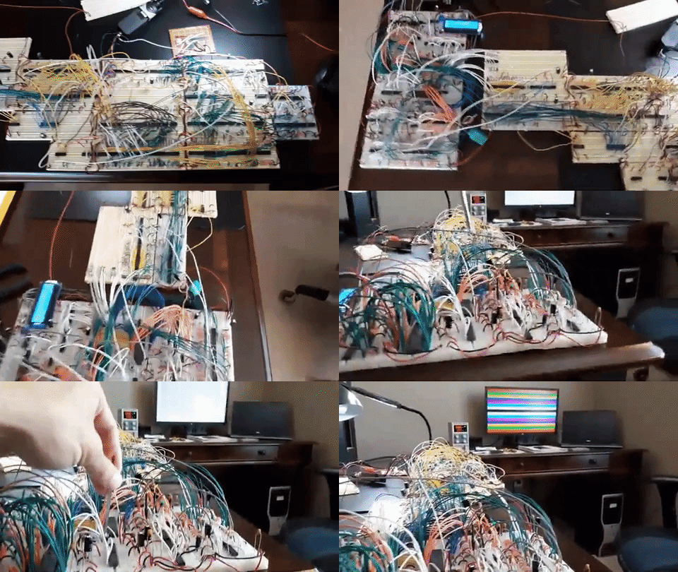
Vectron VGA generates a 640x480@60Hz 3-bit color VGA signal and is designed to interface with the Vectron 64 6502-CPU based breadboard computer. It was built with 7400-series integrated circuits. The display is continually refreshed by the contents of a 32KB SRAM chip (1 byte per pixel) that can be updated via random access during active display operation.
The interface can also be used by other devices, such as Arduino microcontroller dev boards (example here).
The effective resolution is reduced to 160x120@60Hz, because anything higher just isn't retro enough for me. :) This also reduces the VRAM requirements and processing overhead of screen updates as an added benefit.
How It Works
Frequency dividing flip-flops reduce the 25.175 MHz clock four-fold to 6.29375 MHz. This causes each pixel to be repeated 4 times on the horizontal axis. Each vertical line is also repeated 4 times to reduce the resolution to 160x120, while still generating a standard 640x480 VGA signal. The crystal oscillator and frequency divider are soldered onto perfboard -- I don't trust breadboards at that speed -- and the 6.29375 MHz signal is fed into the breadboards.
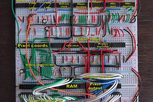
The clock drives a counter that keeps track of the current horizontal pixel position (visible region or not), and through a number of magnitude comparators and line buffers generates a horizontal sync signal and horizontal blanking periods. During the visible portion of the scan line, the current pixel position is translated into an address in a 32KB SRAM chip. The data at that address is converted to analog signals via voltage dividing resistors and sent to the red, green, and blue VGA inputs.
The SRAM address is determined by storing a starting address in a pair of octal flip-flops, then clocking a pixel offset counter, starting from the end of the horizontal blanking period, by the system clock. The starting address and offset are added to determine the SRAM address of the current pixel. Every 4 horizontal lines, 160 is added to the starting address.
A vertical line counter is clocked at the end of each horizontal line. As with the horizontal counter, a number of magnitude comparators and line buffers are used to generate a vertical sync signal and vertical blanking periods.
A flip-flop and series of line buffers allow rapid toggling between "display" mode and "programming" mode for updates to the display. Each pixel can be individually addressed and updated at will via the interface. Using the interface is quite simple on the software side. For the 6502, updating a single pixel looks like this:
; Set VGA generator to "program" mode.
lda #$01
sta $00F8

; Load data to VRAM.
lda #$00
sta $0006 ; Clock lower address flip-flop.
lda #$14
sta $0007 ; Clock upper address flip-flop.
lda #$01
sta $0005 ; Clock data flip-flop.
lda $00F9 ; Pulse SRAM write enable pin.

; Set VGA generator to "display" mode.
lda #$01
sta $00F8
I also have a working example for Arduino boards here.
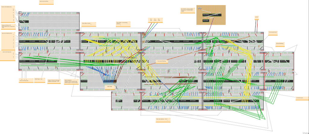
If you would like more details than are provided in this high-level overview, see the circuit diagram in the Media section.
Media
YouTube video: https://www.youtube.com/watch?v=riF9NnIJbLo
Circuit diagram:
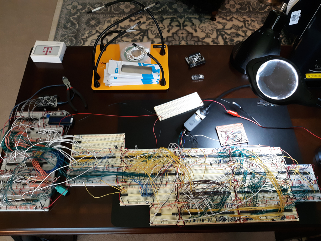
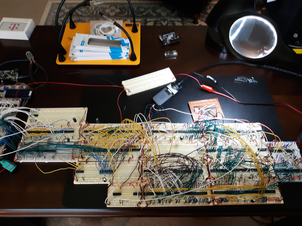
You may notice some free space on a few of the breadboards. You may be able to tighten the design a bit, but I had to space things out to prevent serious electromagnetic interference issues. If any of the high speed switching lines (e.g. address and data) run parallel to one another over long distances, you'll get pixels that randomly flicker and other visual anomalies. Space things out and keep high speed lines short and it'll be a nice stable image generated.
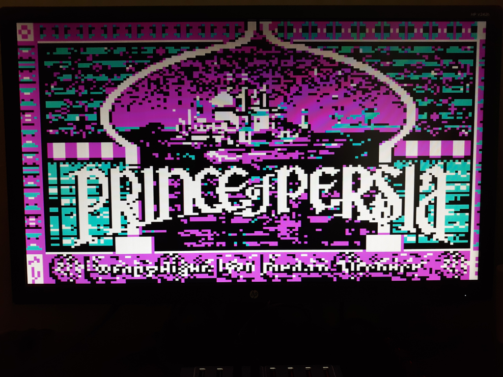
Prince of Persia title screen:
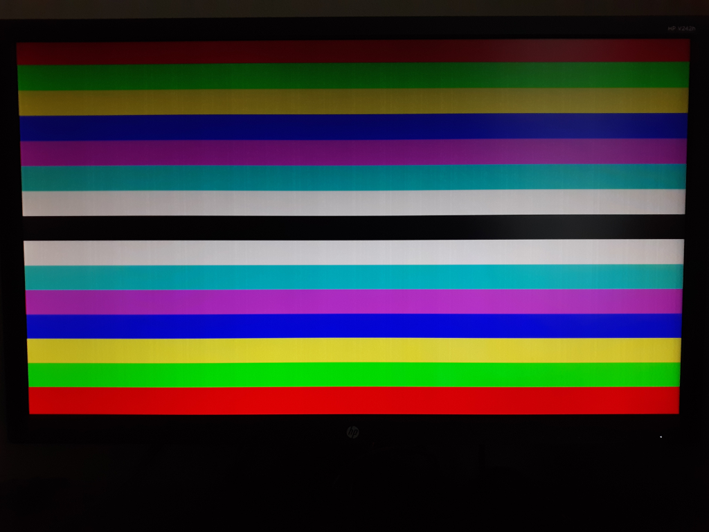
Color bars test, showing all 8 glorious colors.
6502 code to generate color bars is here.
Full setup (Vectron 64 on the left):
Vectron VGA:
Bill of Materials
- 9 x 2.2kΩ Resistor
- 3 x 357Ω Resistor
- 3 x 100Ω Resistor
- 1 x 220Ω Resistor...
 Nick Bild


 Marcel van Kervinck
 zpekic

 teardownit
We get results, eh?
Man , the color scheme on that PoP splash screen brings me back.