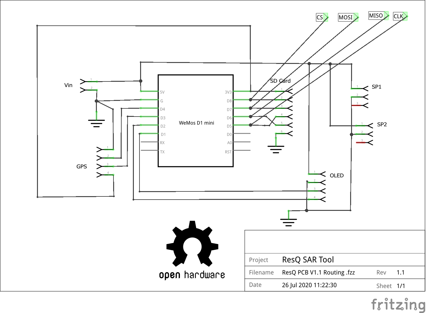
I've tested out the PCBs now and they are GREAT! for my first attempt I am super pleased that they work as intended and now reside in some developing new 3D printed enclosures. With those done I wanted to finalize the schematics and Gerbers but I just couldn't get Fritzing to play nice. For reference here is the original schematic...baaaaad

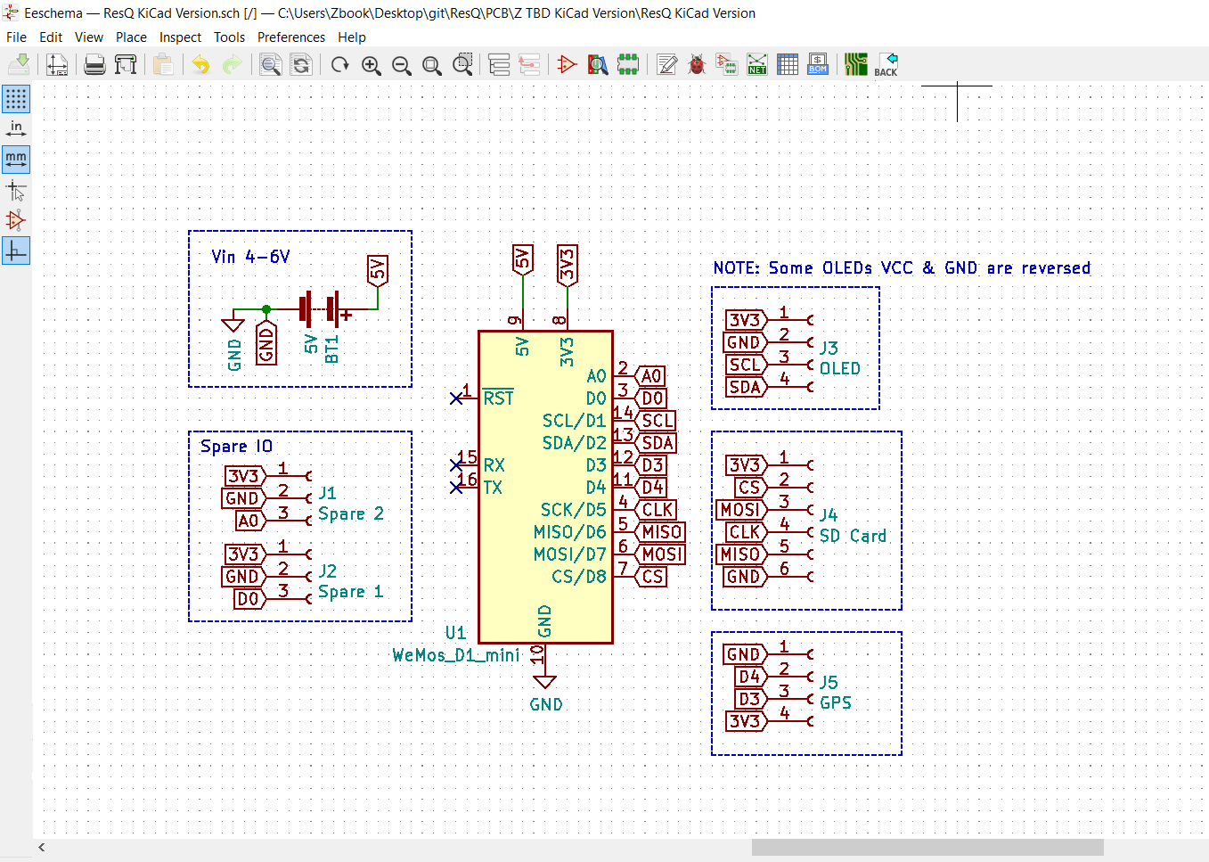
So...I finally bit the bullet and watched a bunch of YouTube videos last night. This evening I fired up KiCAD and this is what I was able to do with no previous experience in about 2 hours.

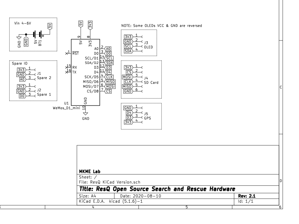
And it prints to this:

Not perfect but a heck of a lot better for sharing I think.
I haven't yet routed the new board but I did correct the previous oversight and not OLED feeds from 3v3 instead of 5V. I went over all the connections twice and it seems solid so all the files are in my Github Repo now. At least this schematic will be much better for anyone to use.
I also included the spare signal wires which are not actually routed on V1.xx boards (needs bodge wire to use them). Spares are 3V3 now instead of 5V used on V1.xx
i ween
 Eric Wiiliam
Discussions
Become a Hackaday.io Member
Create an account to leave a comment. Already have an account? Log In.