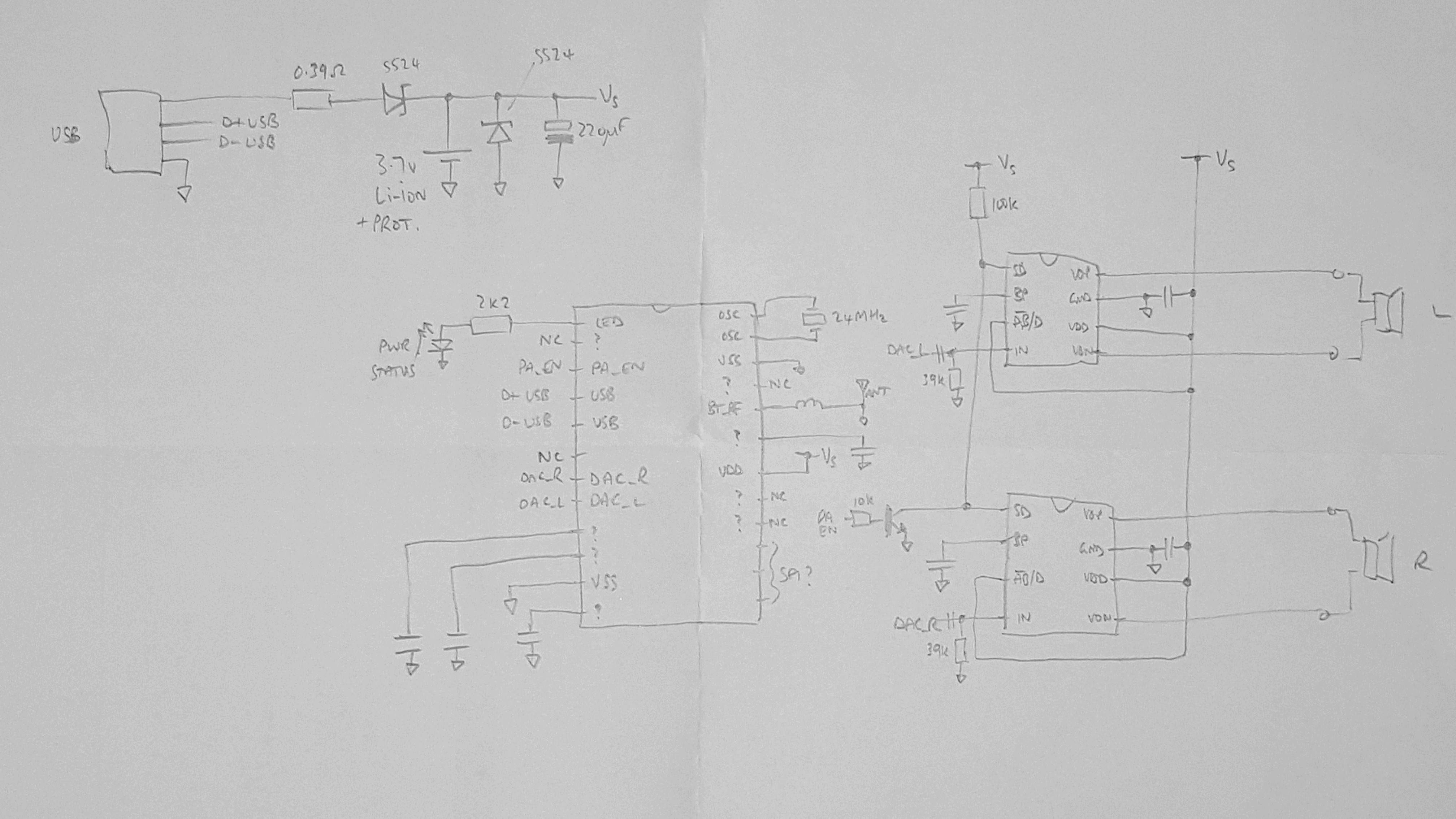
The board is labelled v1.8, which seems to be less common on the web than the v1.6 and v1.7. The differences seem to be to do with controlling the amplifiers' SD pins - everything else looks pretty much identical.
The amp chips have a shutdown pin (pin 1) which appears to be active high: pulling it low or leaving it floating turns the amp on. As standard they are controlled via an NPN transistor (S8050) level-inverter from the BT module (pin 3), as evidenced by the slight pop when starting/stopping audio.
The BT chip itself doesn't appear to have an enable/shutdown pin (at least the AC6905 doesn't).
Charging is really simple: 5V from the USB connector is dropped first through a 0.39ohm current limit resistor, then through a SS24 Schottky diode (~0.5-0.6V) and then connected to the Li-ion cell. That's why the cell needs protection: because the charge circuit can float up to ~4.5V, higher than is safe for Li-ion. Charging from flat (e.g. 3.0V) is slightly terrifying: about 1.3V gets dropped across the 0.39ohm resistor, meaning the charge current is 3.3A! That's about 2.4C charge rate for my single 18650 cell. Eeek. Also about 4W gets dissipated by the tiny chip resistor - that'll get pretty toasty I bet. Ah, but of course USB is limited to about 100mA for a standard peripheral, so this circuit relies on the USB host doing the current limiting correctly. Still eeeek.
The obvious place to insert a power switch, therefore, is just downstream of the battery/charging, but before the BT and amplifiers. Sounds simple, but the layout is a bit inconvenient.

I had a go at tracing out the schematic, see above.
Discussions
Become a Hackaday.io Member
Create an account to leave a comment. Already have an account? Log In.