 PMercier
I had the connectors, but what to do with connectors. Last time I checked, they are used to connect things together...
For the next steps I needed to extract the bus connector outside the scope to play with it.
So let's do a testing board as my very first PCB. Seemed easy to learn the routing process as there was a lot of tutorials and resources.
EasyEDA was a good candidate to start with. I had one problem to solve that got on my nerves : the connector was unknown in the library. I had to import it myself from mouser or other. It was a pain as am a Linux guy and whatever i found used Windows to do so. Wine wasn't a big help. I had to create a Window 10 VM just to import one connector inside EasyEDA. But in the end i had the connector in the EasyEDA shared libs.
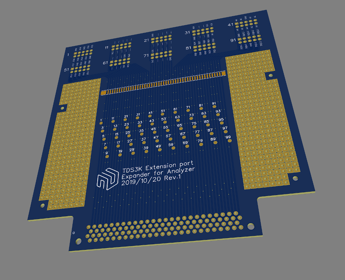
Many iteration of the board later, many hours of learning by trial and errors, many hours of looking resources about making a good digital board, i had a board to convert the 100 pins connector to 10 x HE10 headers plus prototyping space and exposed signal traces to solder on if required.
 3 week later, some soldering, and it was now the time to get on the scope screen what was going on inside himself.
But first, I had to test the serial port again :)
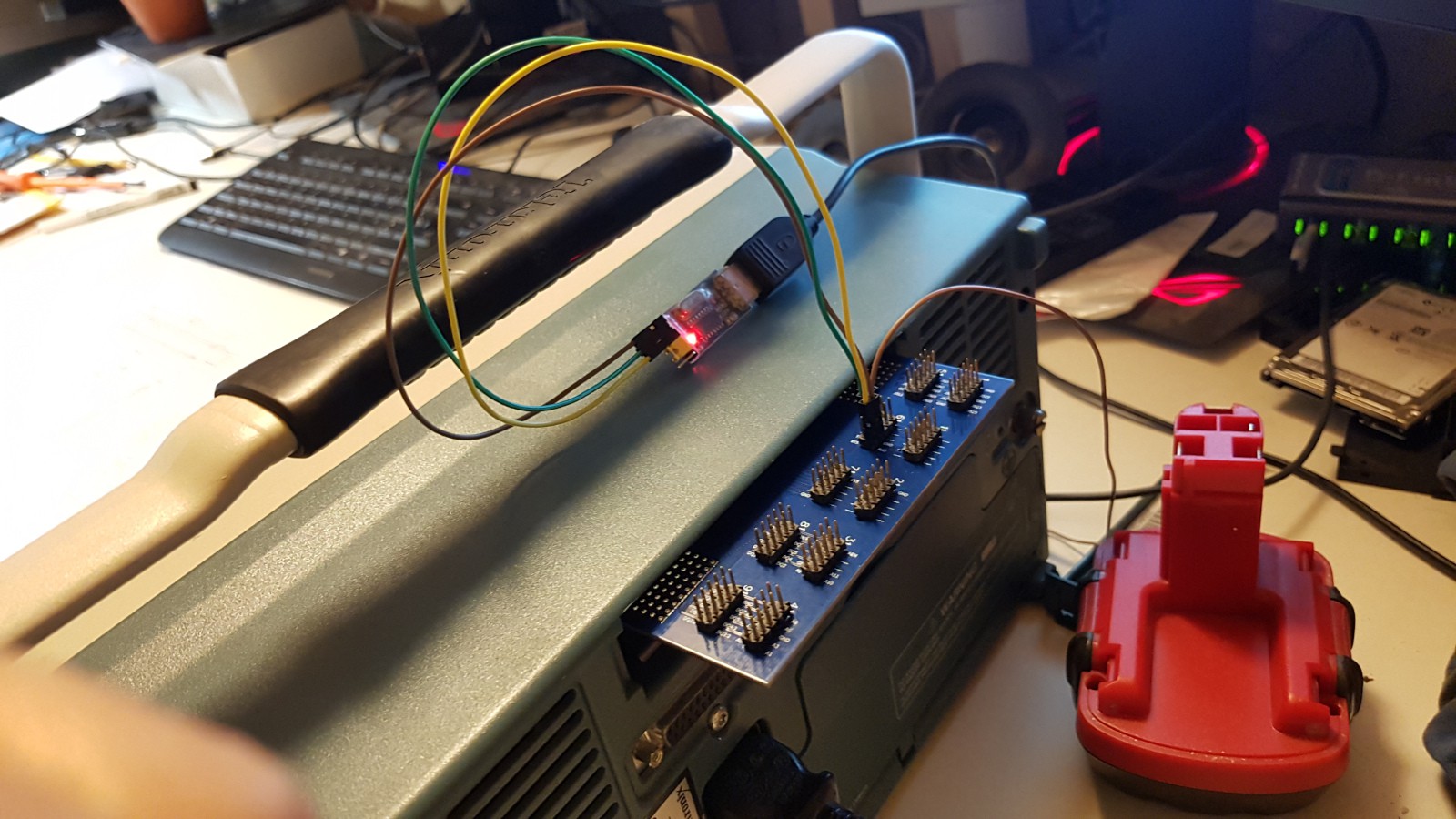 It feel safer to work and poke inside the scope.
Oh and it worked like a charm. Happy with my first PCB and ... gave me the need to make more PCB like that ... my wife will hate me sooner or later ...
Serial work but still no change for the *IDN?.
PS: Later on I found that i made errors with the annotations on the card, but too late, it was sent i production. A least the headers pins are numbered correctly.
Discussions
Become a Hackaday.io Member
Create an account to leave a comment. Already have an account? Log In.