So I decided to improve my by design and soldering skill by only choosing 0603 sized components (Which is retrospect a size that I won't go further unless I get a magnifying glass or a microscope).
I wanted to have to boards one on top of each other to clean up the design and make it appear less "hacky" and I recently discovered the TTP223E Touch control ic, so I don't wanted to use a typical pushbutton to validate the access. So I basically cloned the blue pill design and added the ic:
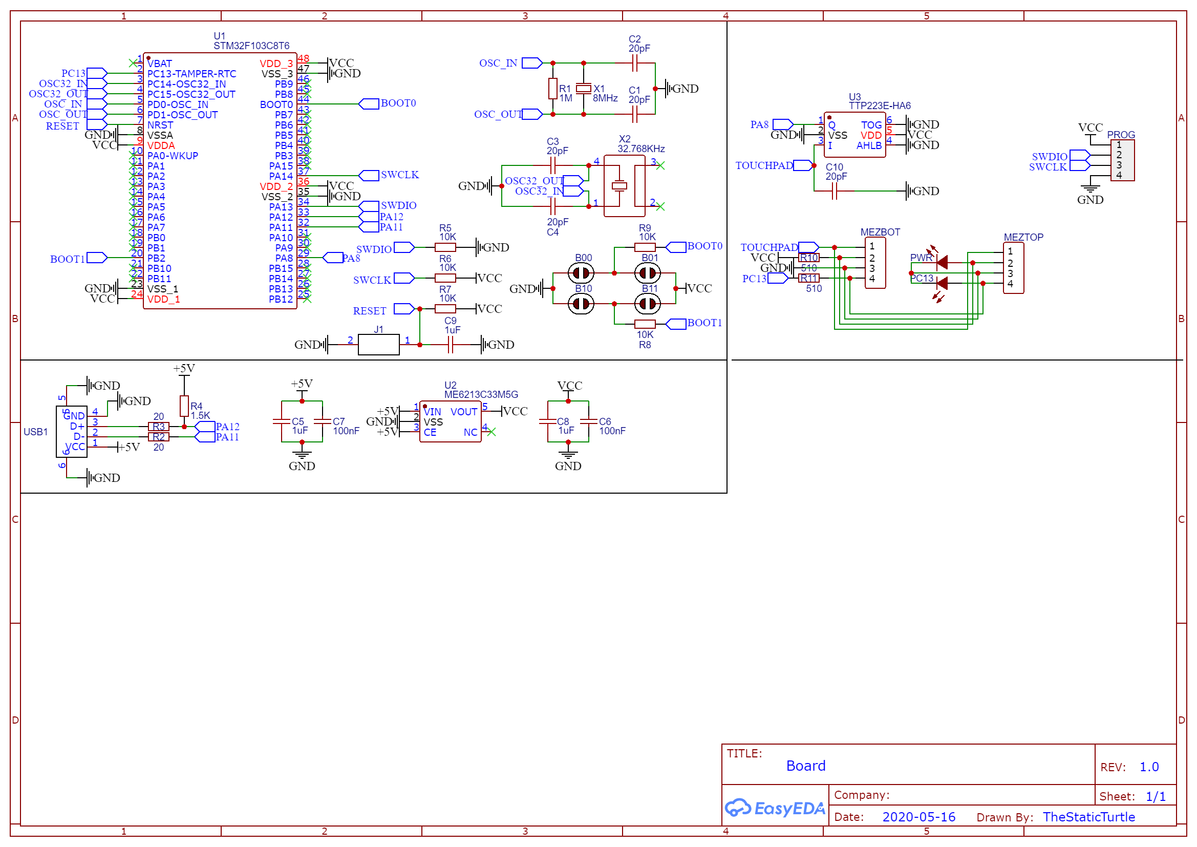
I replaced the BOOT0/1 header with tiny pads that you solder to change the position, the USB connector to a USB A male one , I also tried to solder a metal dome for the reset button but that was a TOTAL failure of course I chose LCSC as my component provider (Partly for the shipping discount when you order via JLCPCB) and here is the BOM list the PCB design was by far the most challenging one that I did since I tried to do my best to reduce the board size (which cause me some problem during assembly later) at the end I submitted a panelized version of this board:


The bottom and top board are connected to allow me to test everything without the top board being in the way. After finally receiving my PCB from JLCPCB I snapped on board out and started soldering
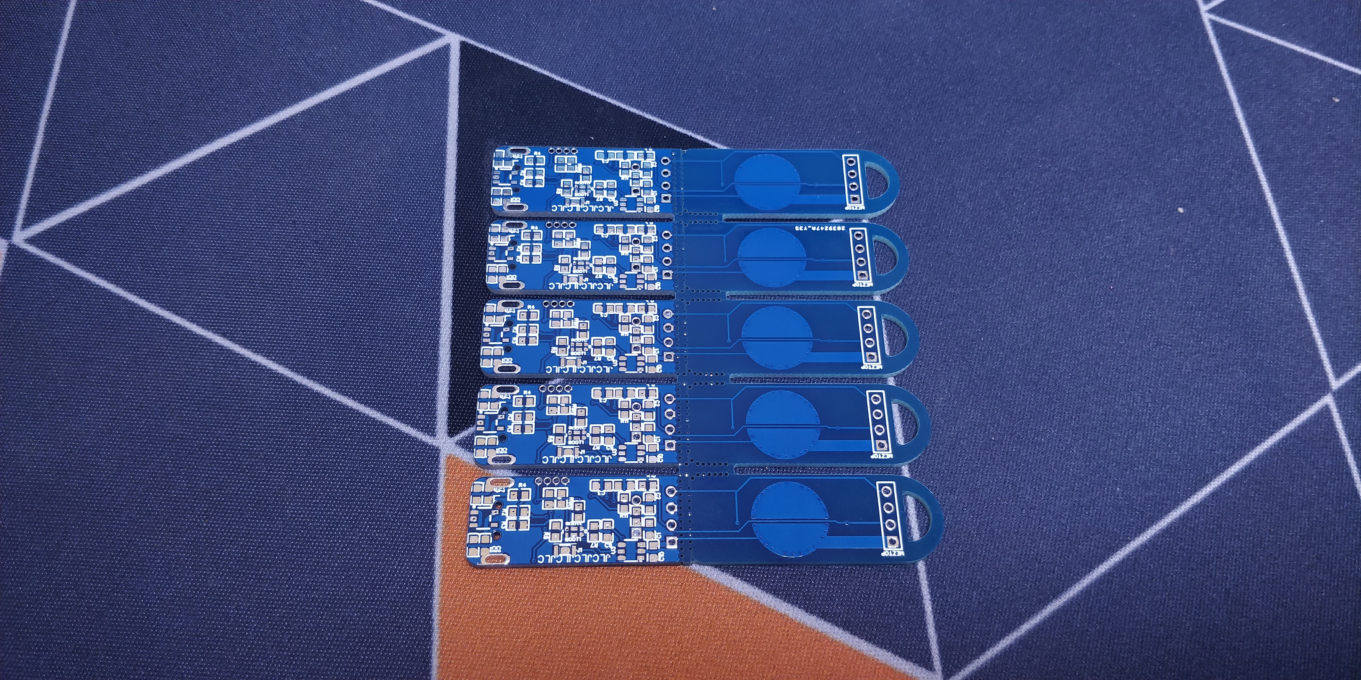
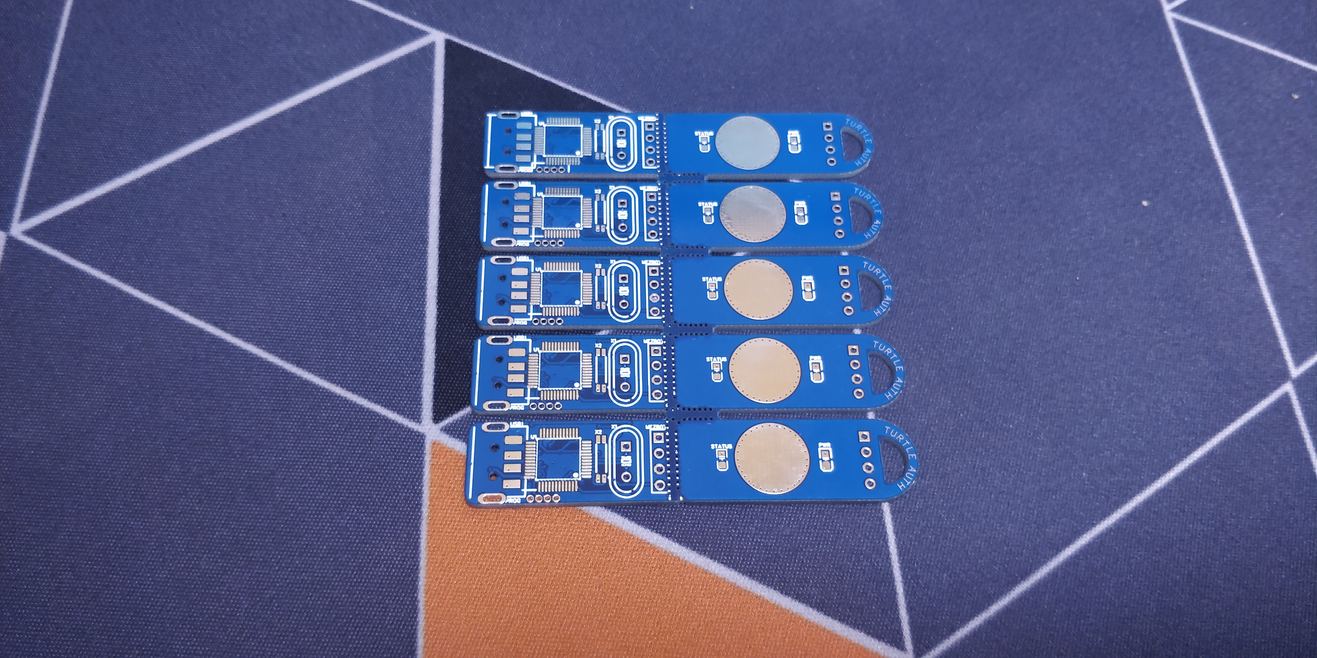
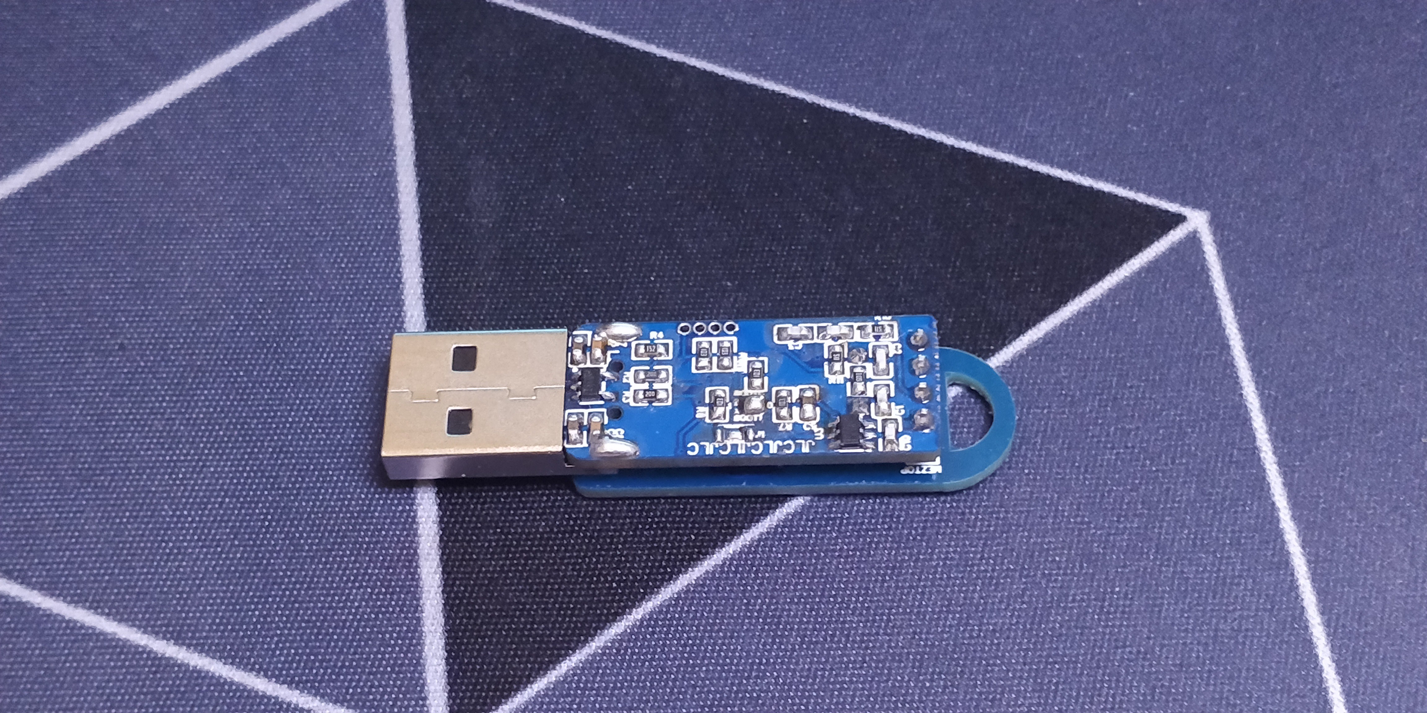
And you can probably see the big mistake that I made, the USB is too far in and interferes with the board (I should really get the real 3d Model) a bit of surgery fixes that. As it turns out gunk doesn't need the 32.768kHz oscillator, so I didn't solder it but left the pads in if I ever want to repurpose the board in the future. After a painful soldering session this was the result and I'm very happy with it:
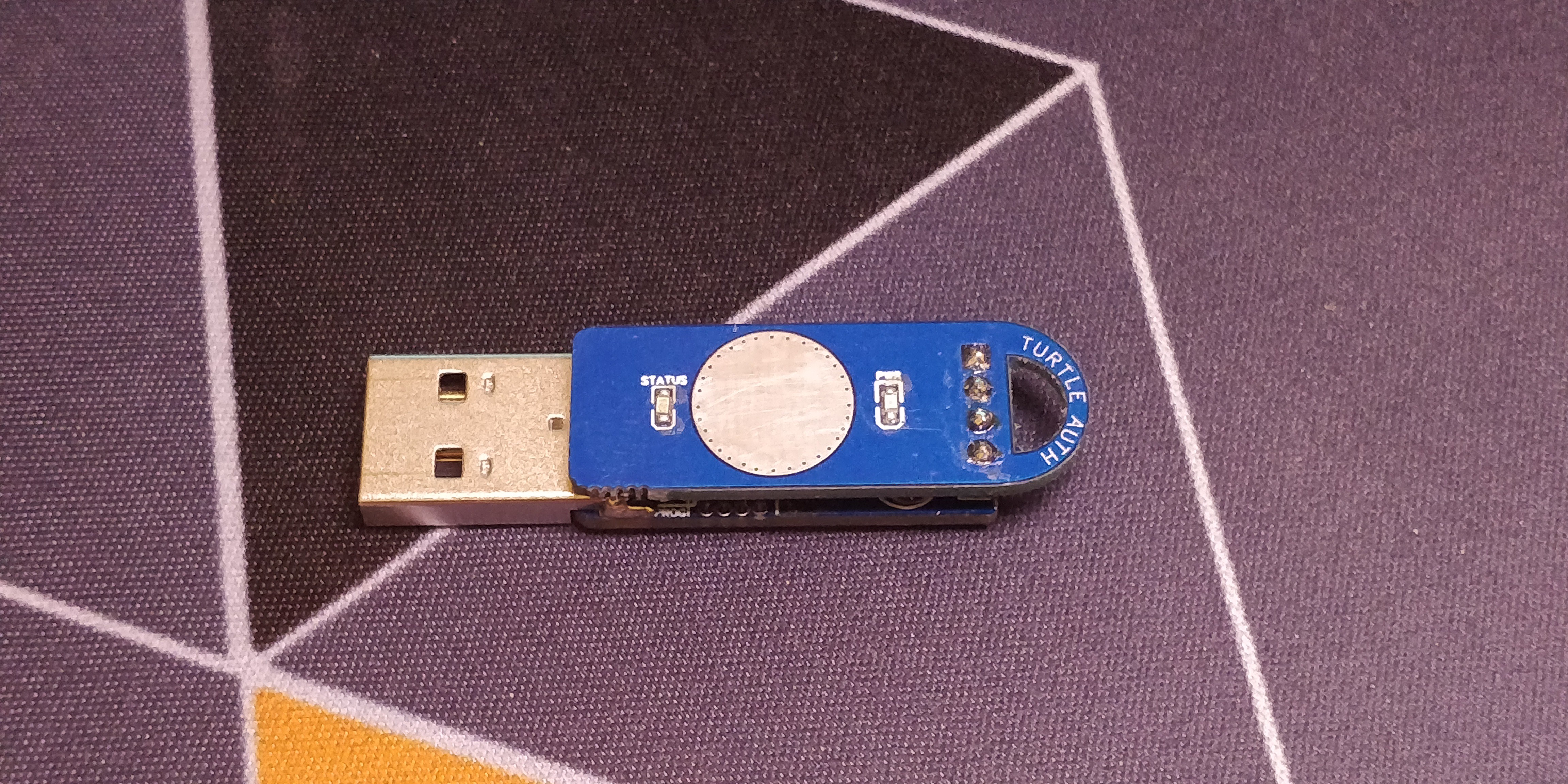
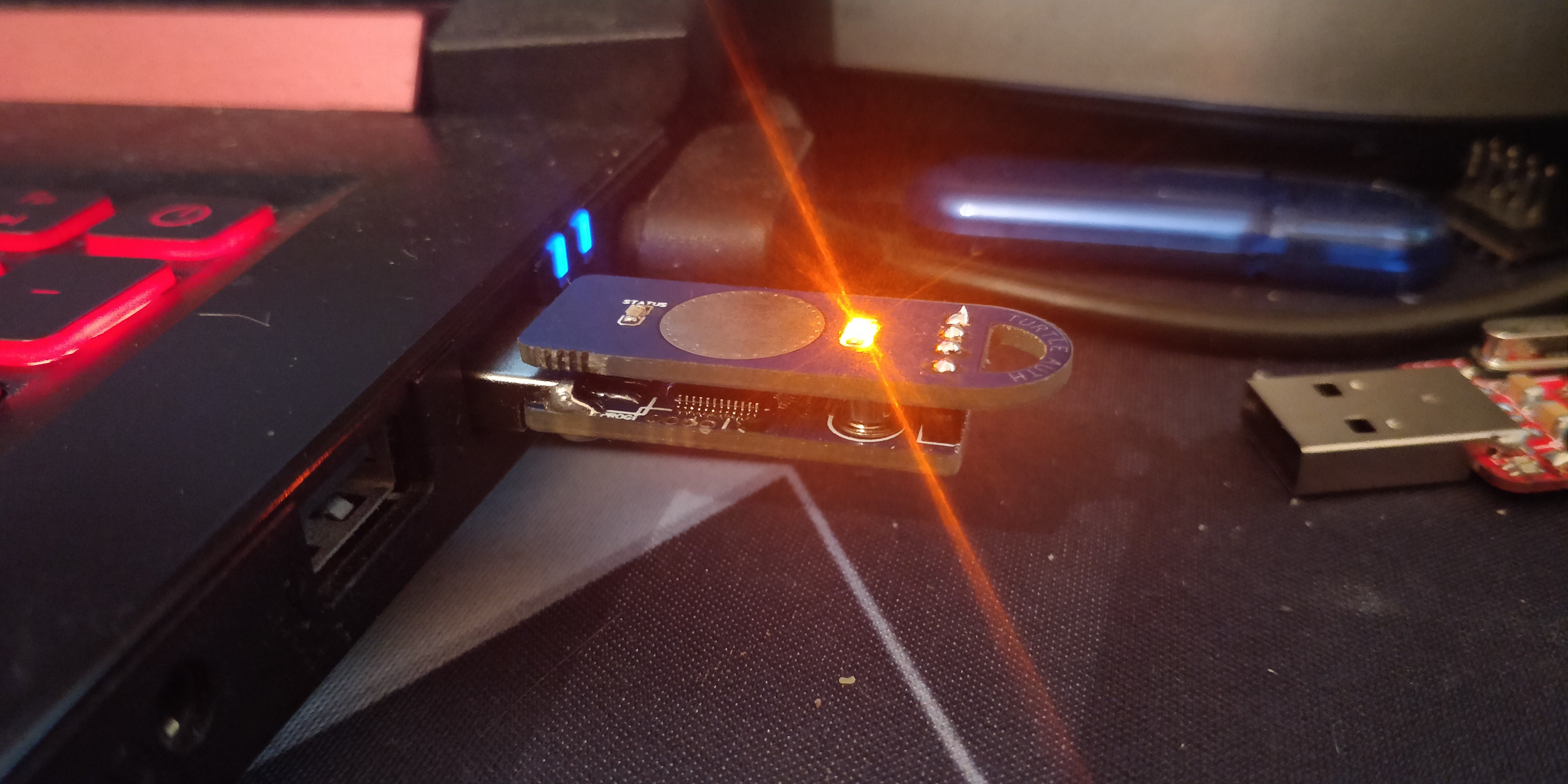
 Samuel
Discussions
Become a Hackaday.io Member
Create an account to leave a comment. Already have an account? Log In.