Dominik Meffert
-
STM32 and Fritzing
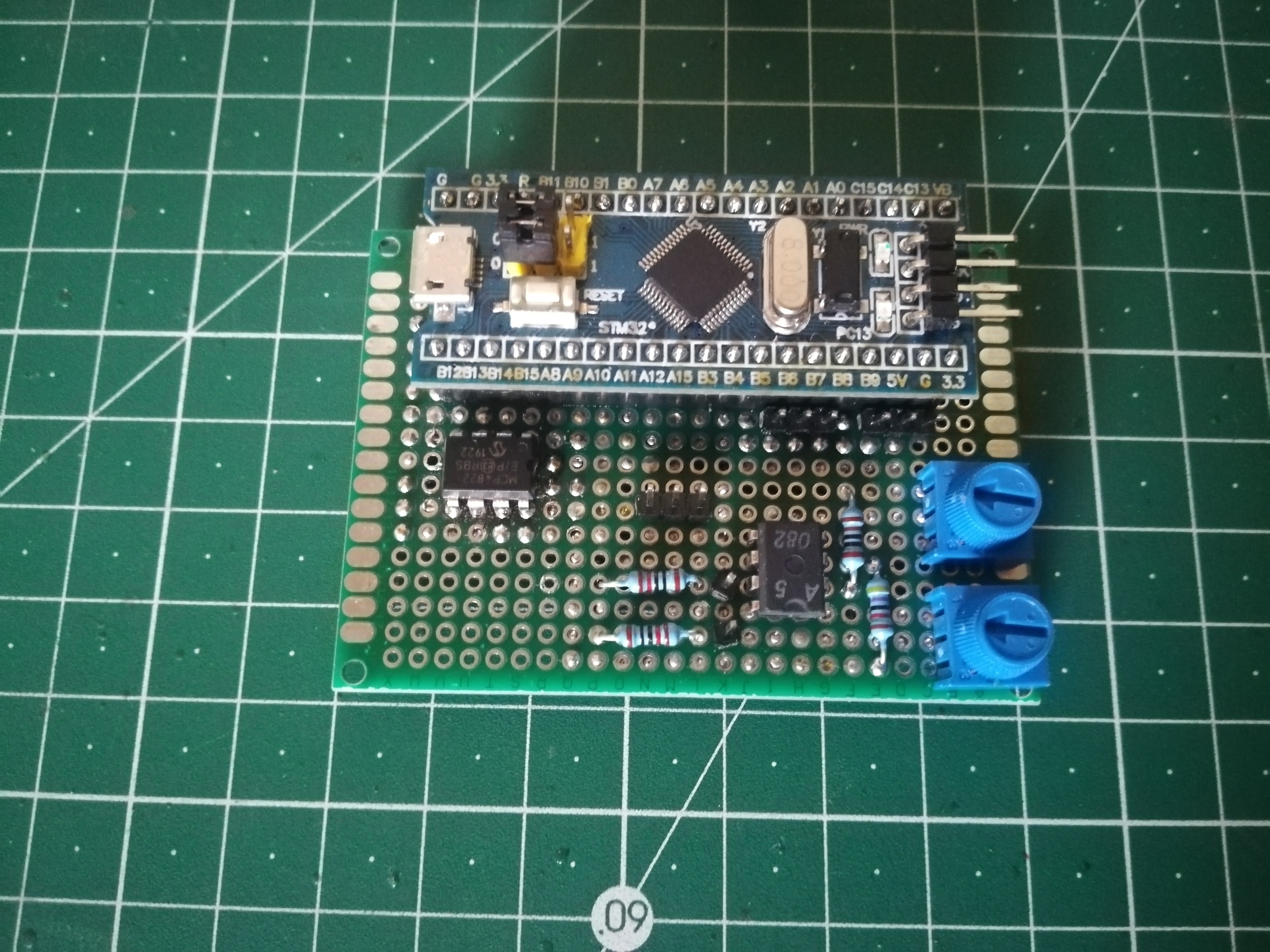
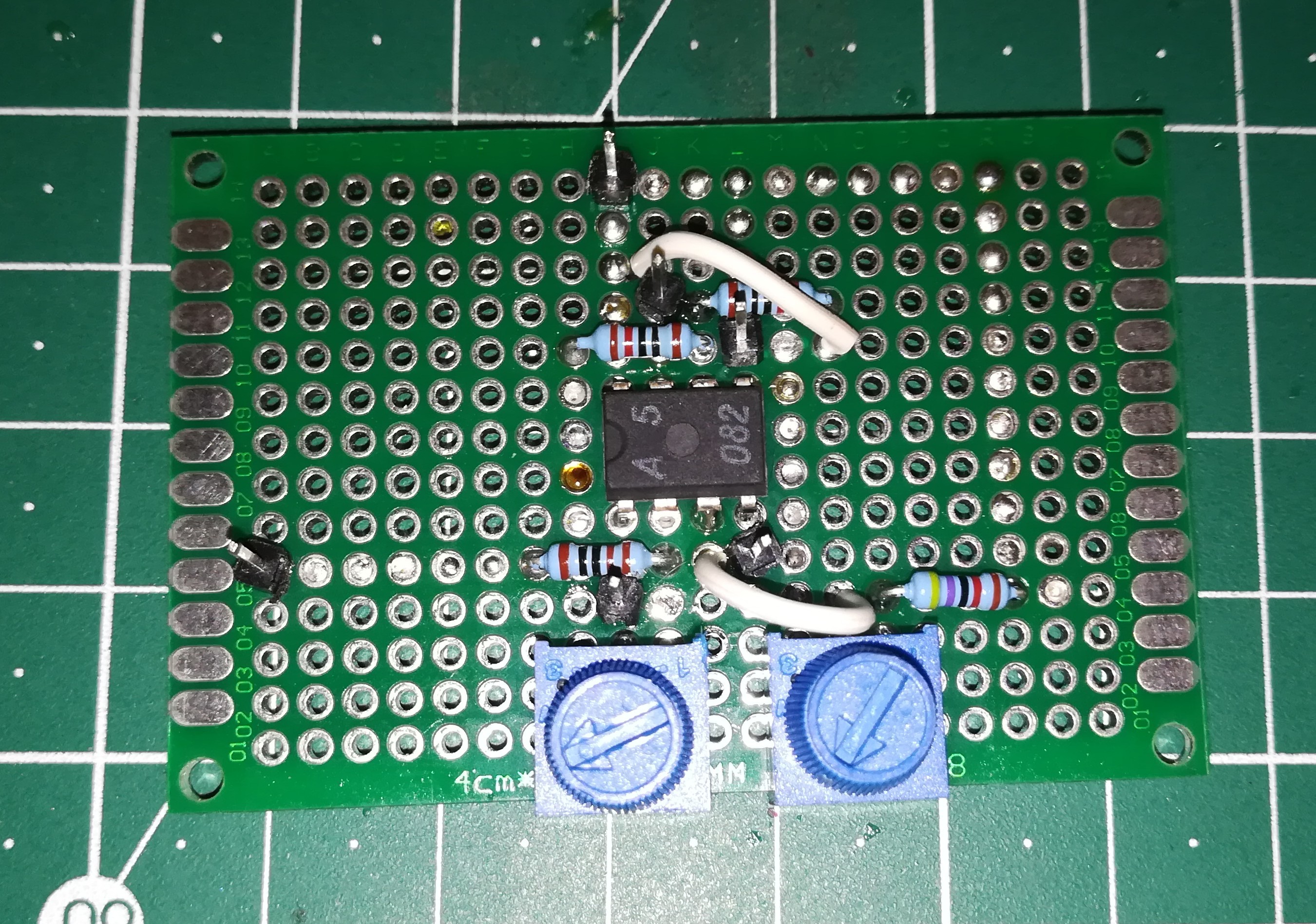
06/17/2020 at 17:00 • 0 commentsI tried to place all components for a single axis on a perfboard including a STM32 which should be faster than the Arduino UNO.
![]()
![]()
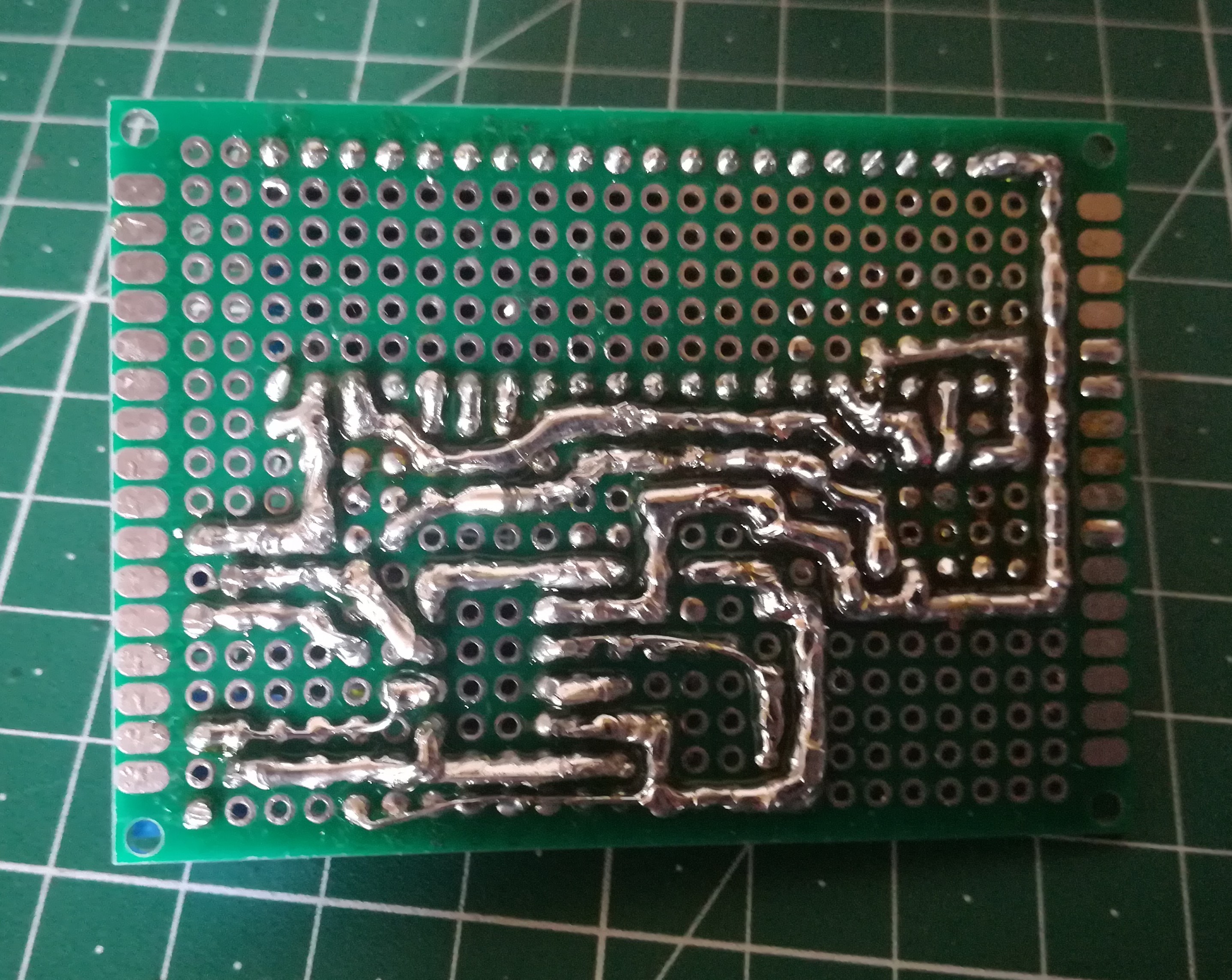
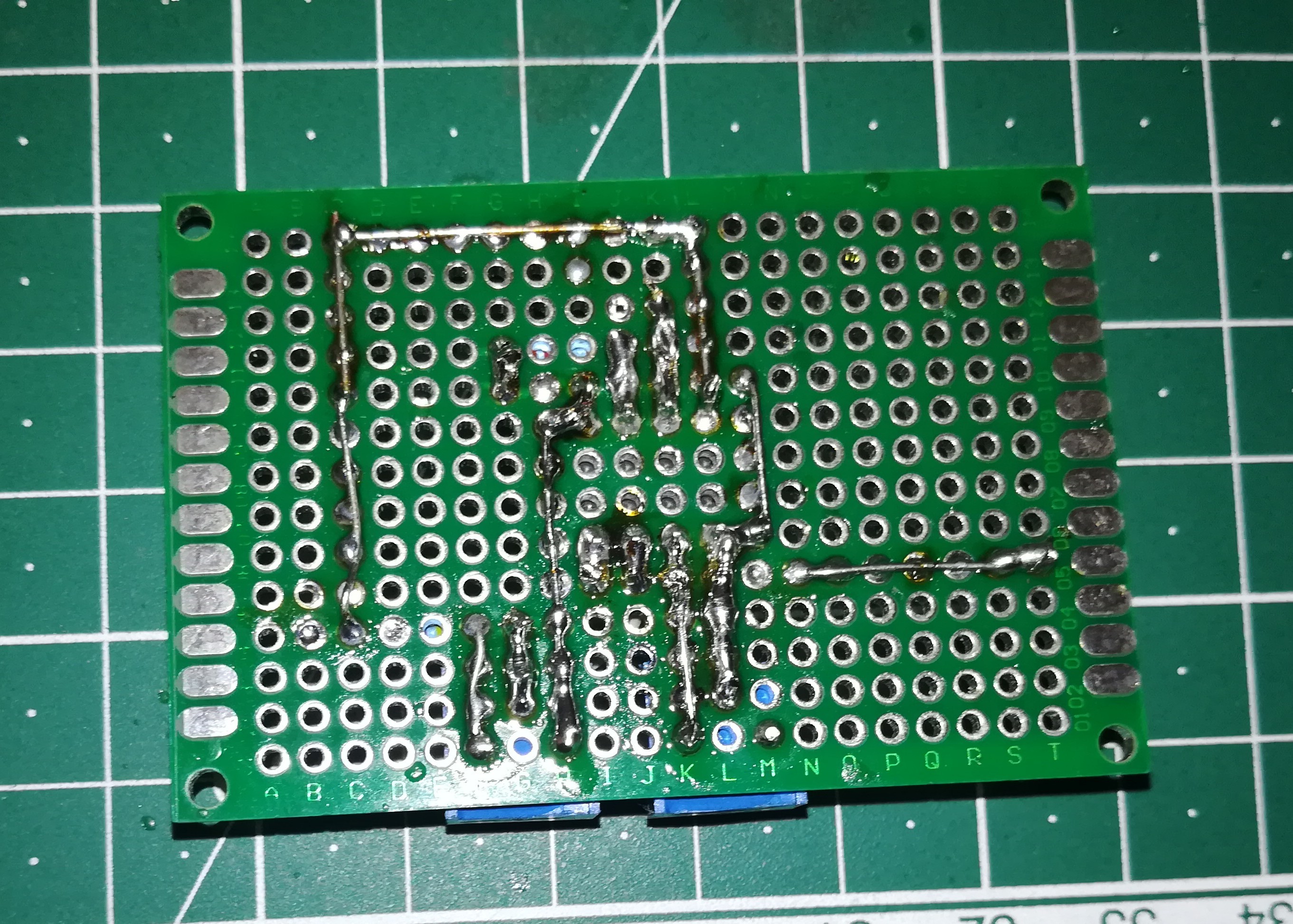
There is plenty room for improvements in soldering the connections.
![]()
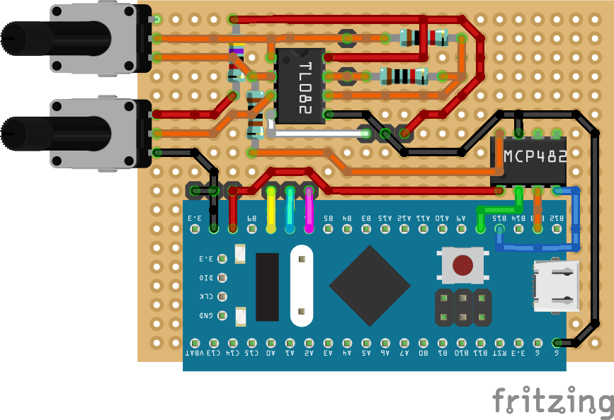
I tested out Fritzing for planning the board on the PC to find the right place for the components and the connections.
![]()
![]()
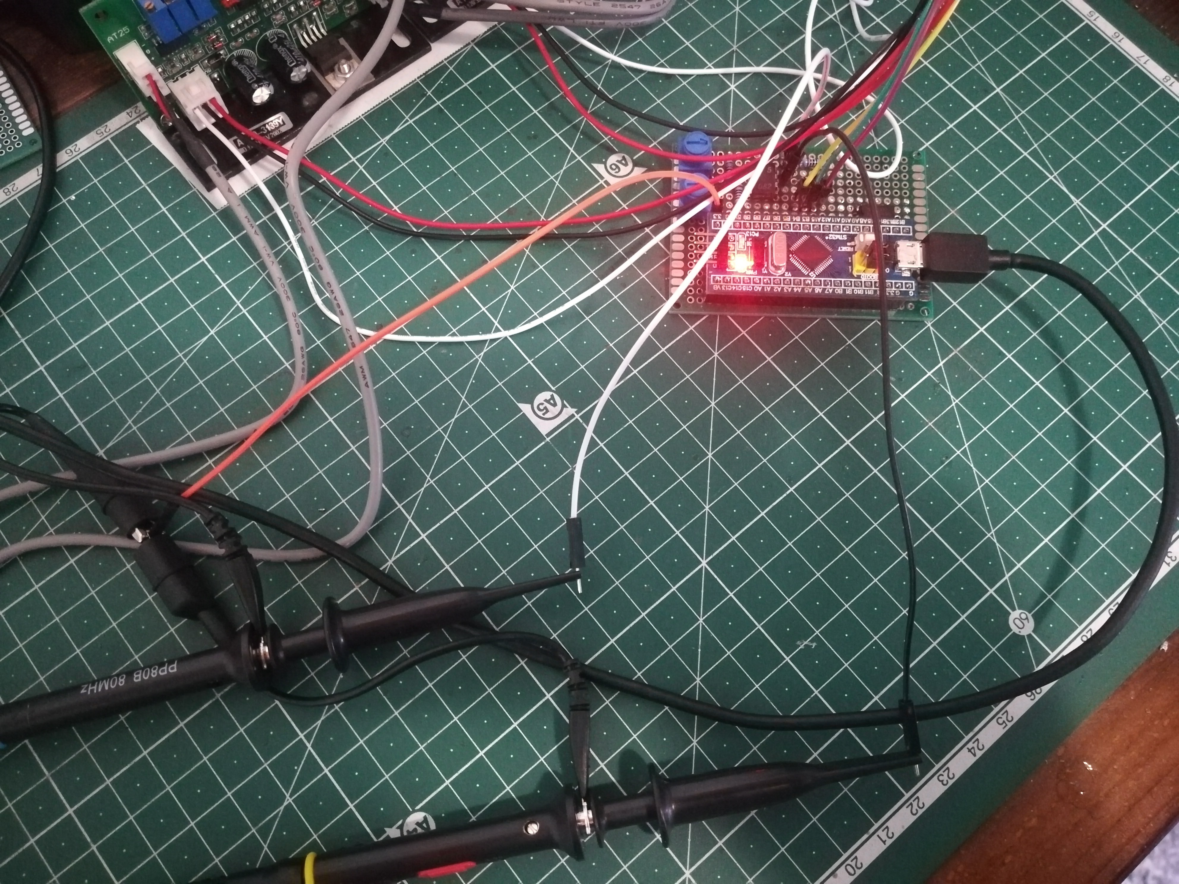
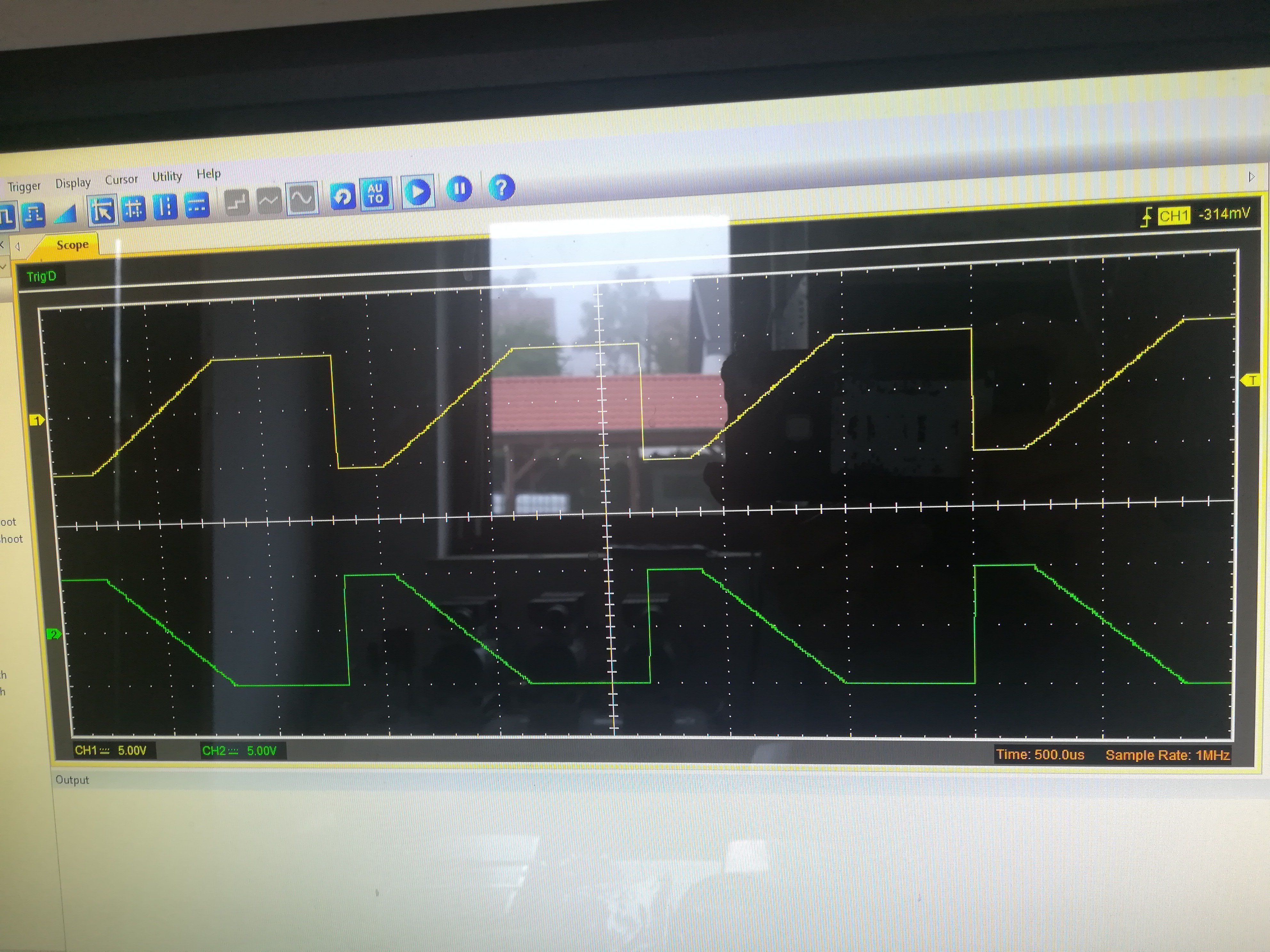
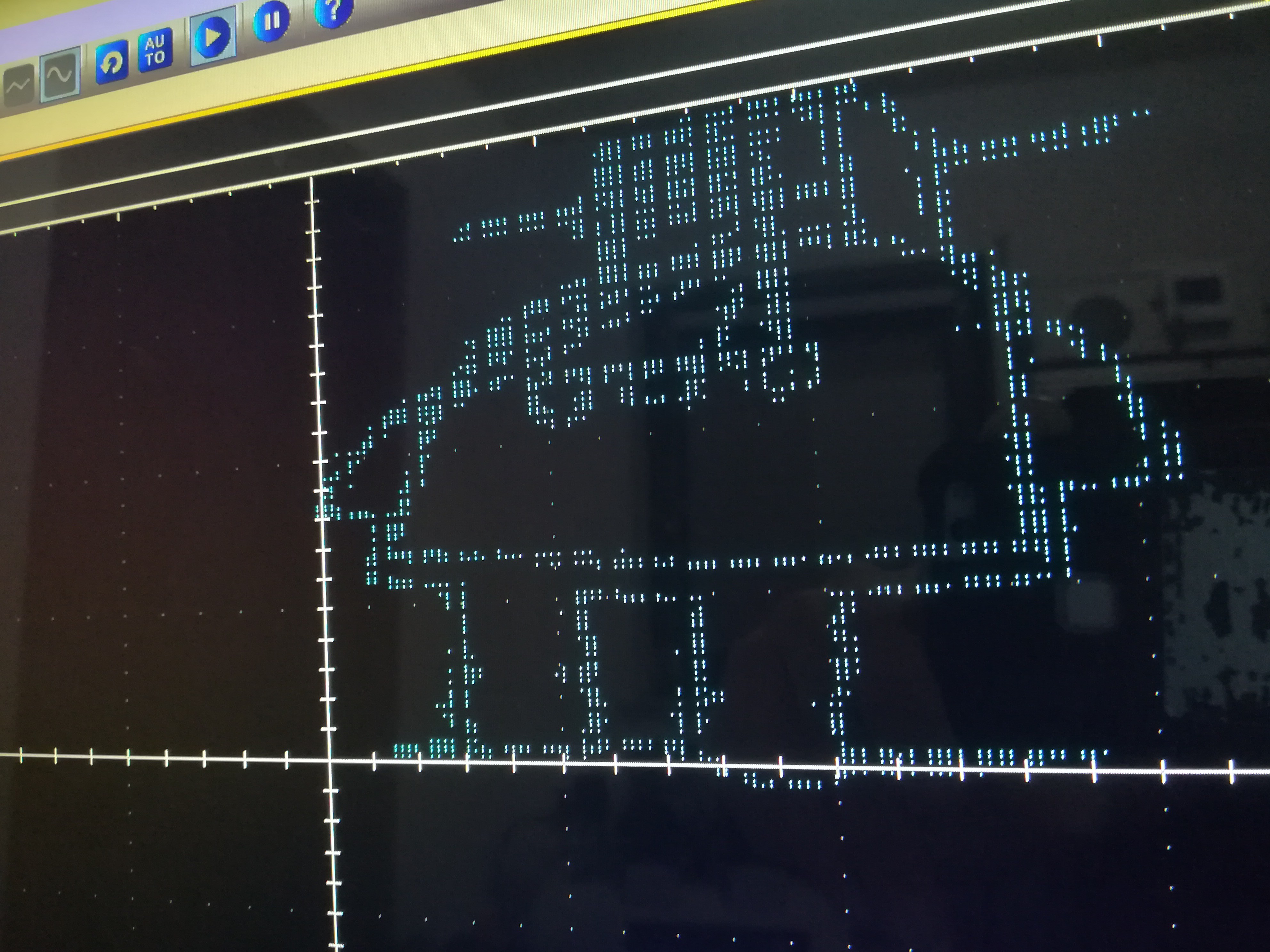
After changing some connections and figuring out how to use SPI on the STM32, the output worked like it should.
-
Processing Step/Dir Signal
06/13/2020 at 16:06 • 0 commentsNow that I know how DACs and OpAmps can be used for creating the right signal for the galvo drivers the next thing will be processing the Step/Dir signal from a machine controller (Arduino CNCShield, Ramps and so on).
For that I want to use at first just an Arduino UNO or NANO to do it in the easiest possible way.
If it turns out that more speed is needed, I can later switch to a more capable microcontroller.
I tried to read step/dir pulses created by an Arduino UNO with another Arduino UNO and it worked so far with up to 60kHz.
For testing the output I tried to drive a servo with the received Step/Dir signal at low frequency.
Reading Step/Dir and sending it to the DAC works, too.
The next thing will be testing with a real Step/Dir signal from a cnc or 3d printer controller and building a cleaner test setup.
-
Testing out the Galvo Kit and learning something about DACs and OpAmps
06/12/2020 at 01:08 • 0 commentsTo see what the galvos look like when they are running I made the first part of DeltaFlo's Galvo Instructable to give them an input signal.
Will read a bit about Op Amps and make the second part, too.
![]()
![]()
I read a few explanations and watched a few videos about what OpAmps are and what they do and built the OpAmp circuit from the Instructable.
I haven't built many circuits so far and this simple circuit was the most complex until now, but I'm really happy that I got it to work and I think building more complex circuits in the future will be a lot of fun :)
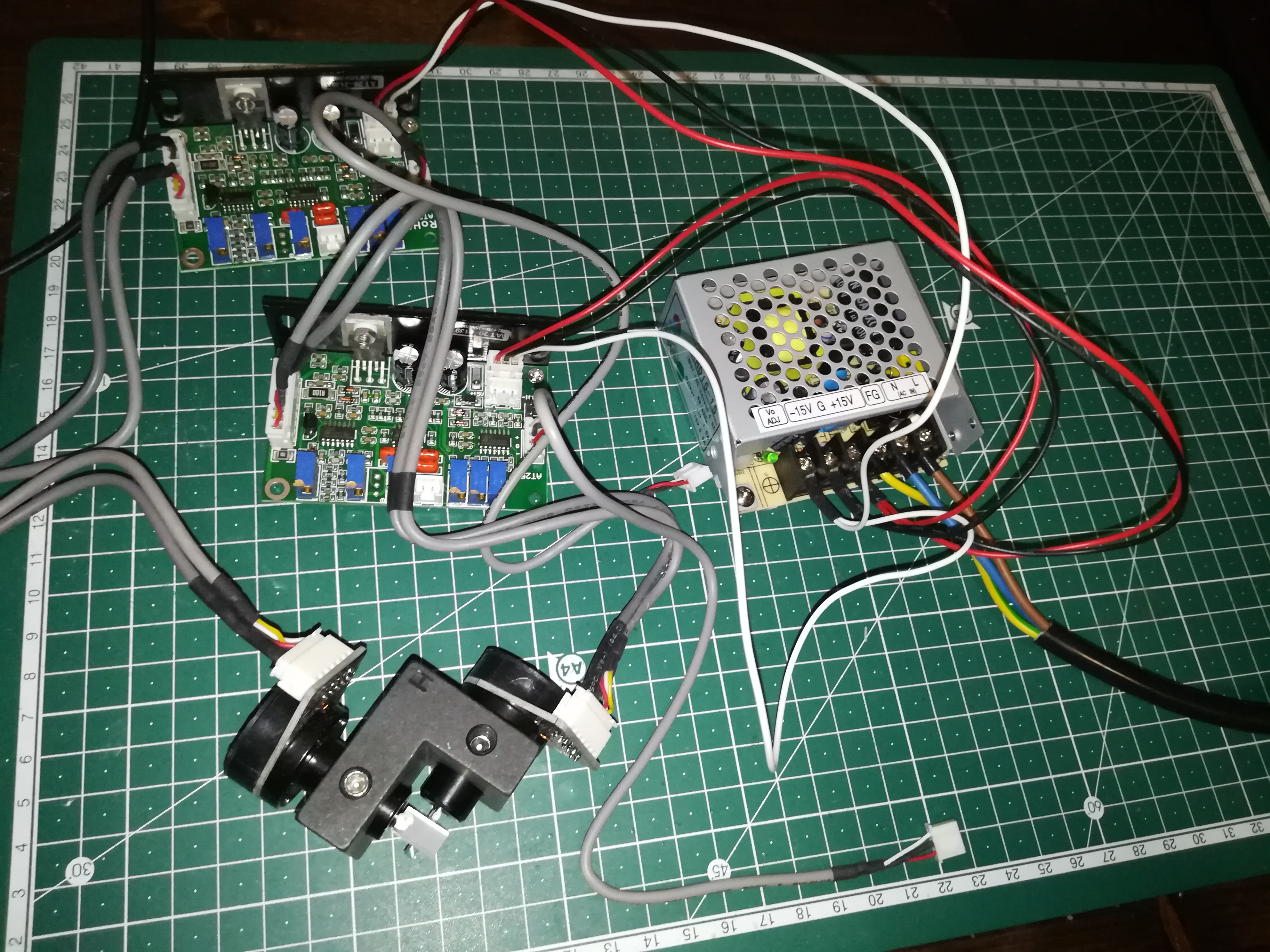
Here is my setup and what the output looked like on the oscilloscope.
![]()
-
Getting Started
06/10/2020 at 23:22 • 0 comments![]()
I bought one of these cheap Galvo Kits from the internet.
![]()
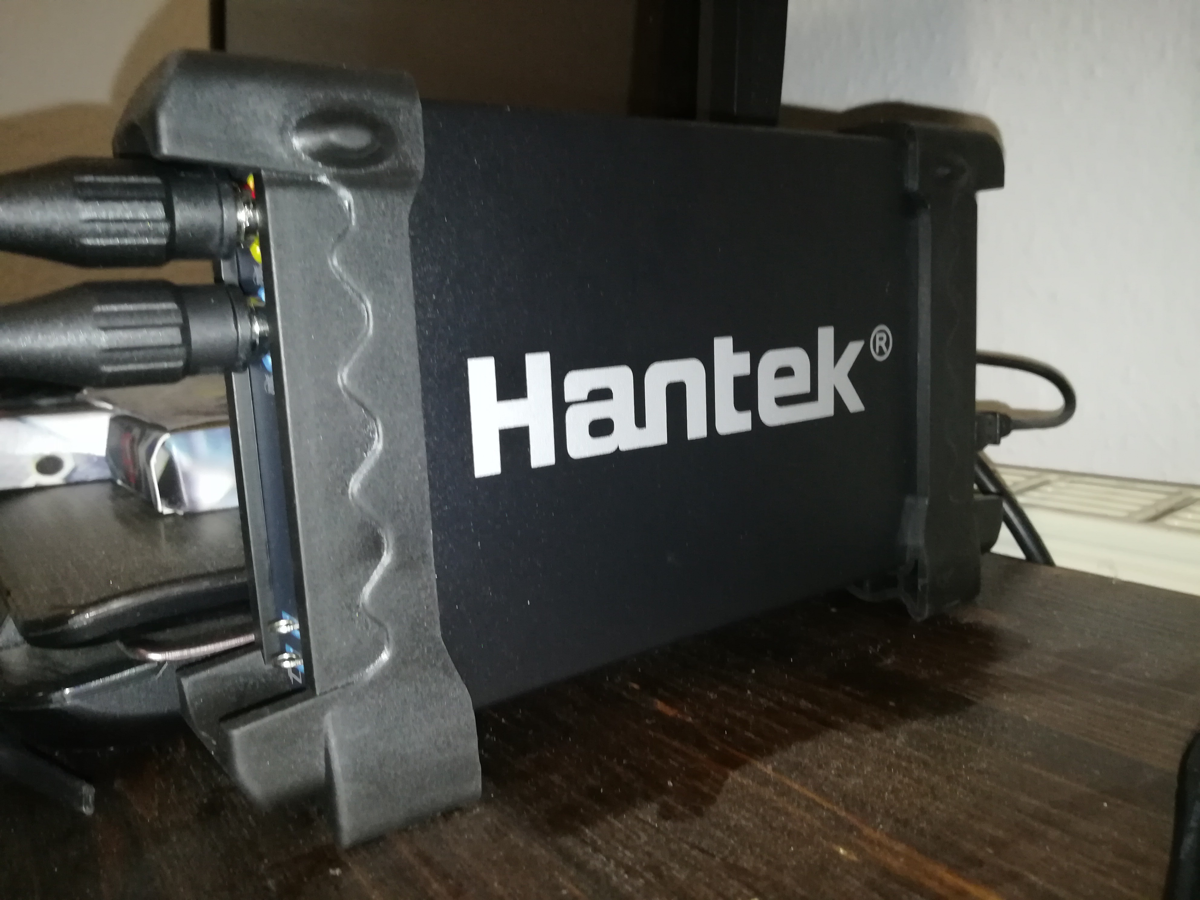
And also a Hantek 6022BE USB Oscilloscope for getting started.
![]()
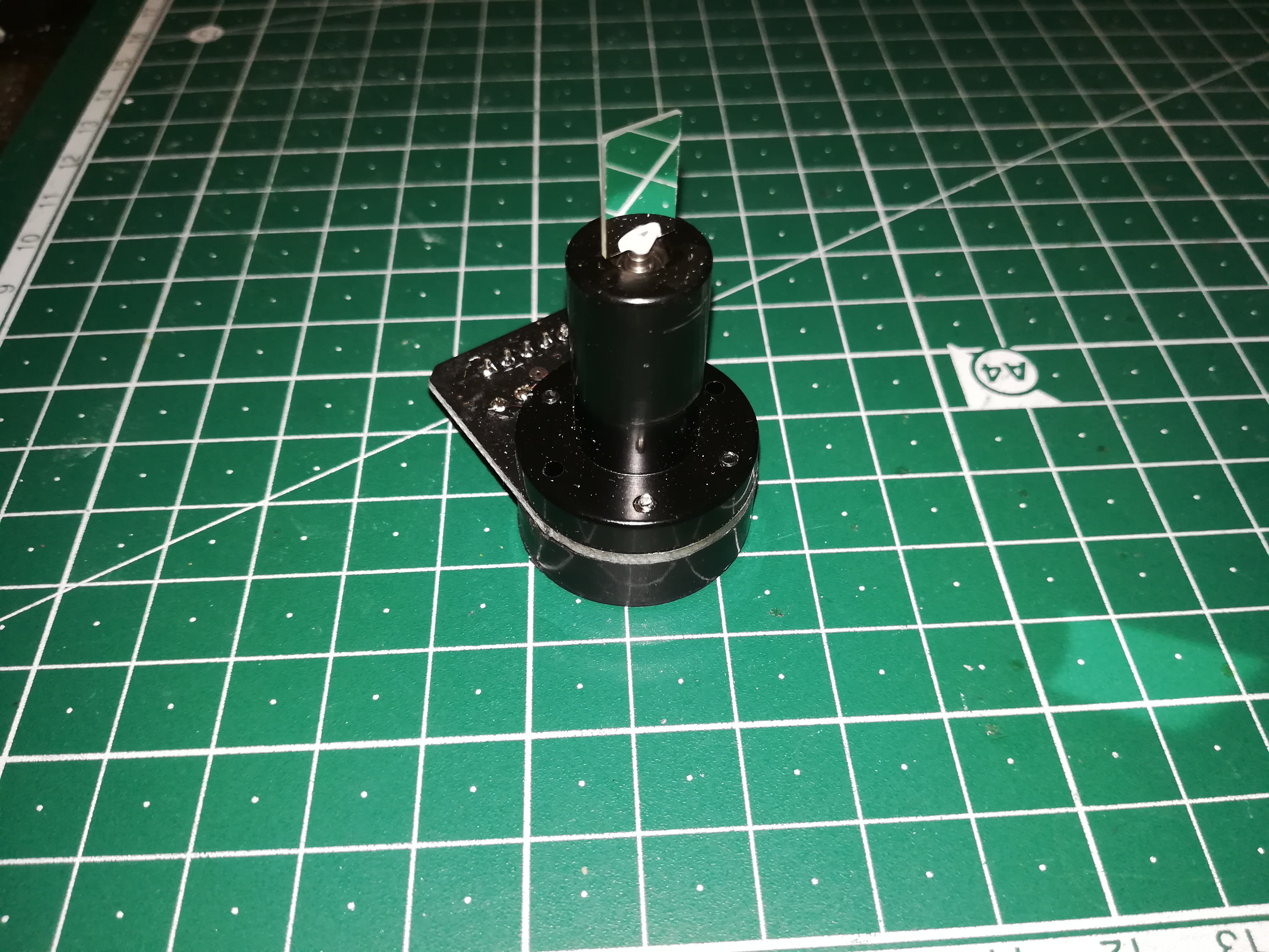
The set includes a power supply with +15V GND and -15V output, two driver boards and two of these galvos.
![]()
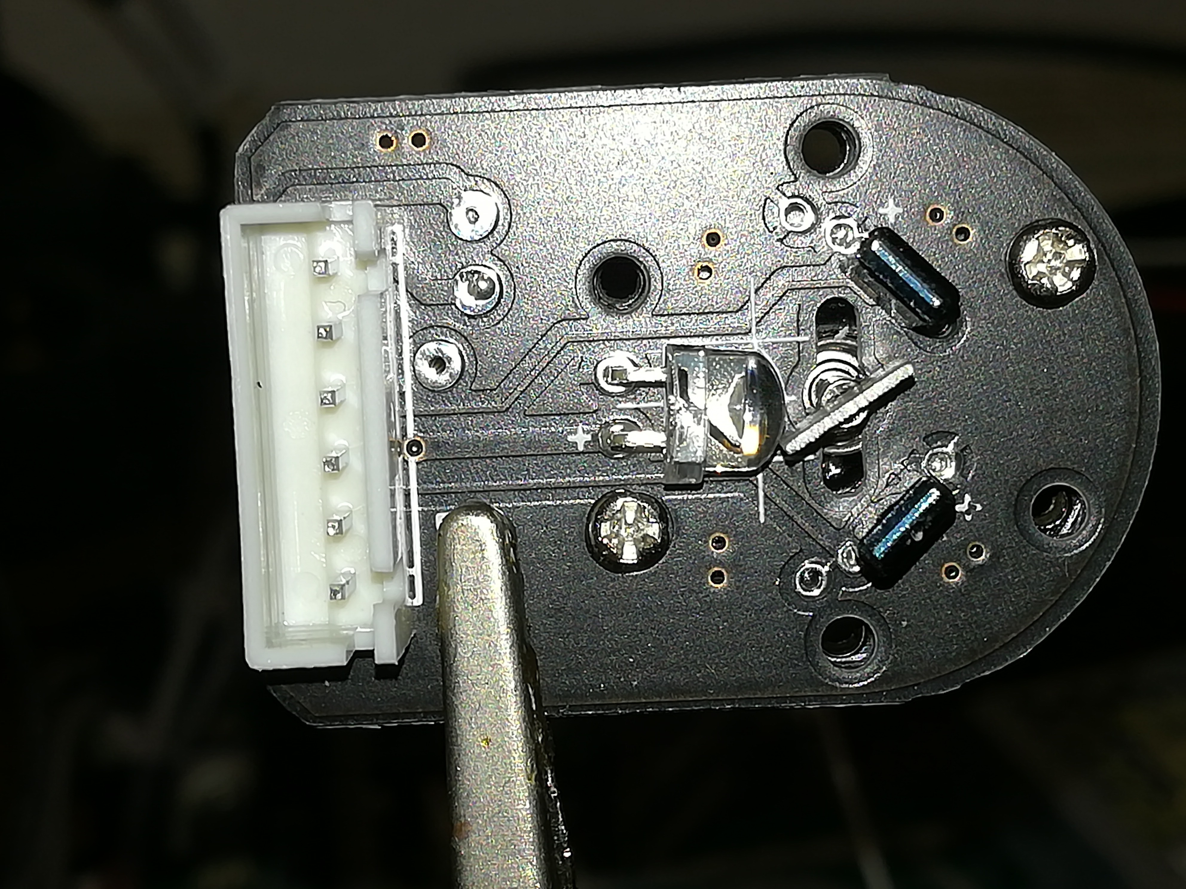
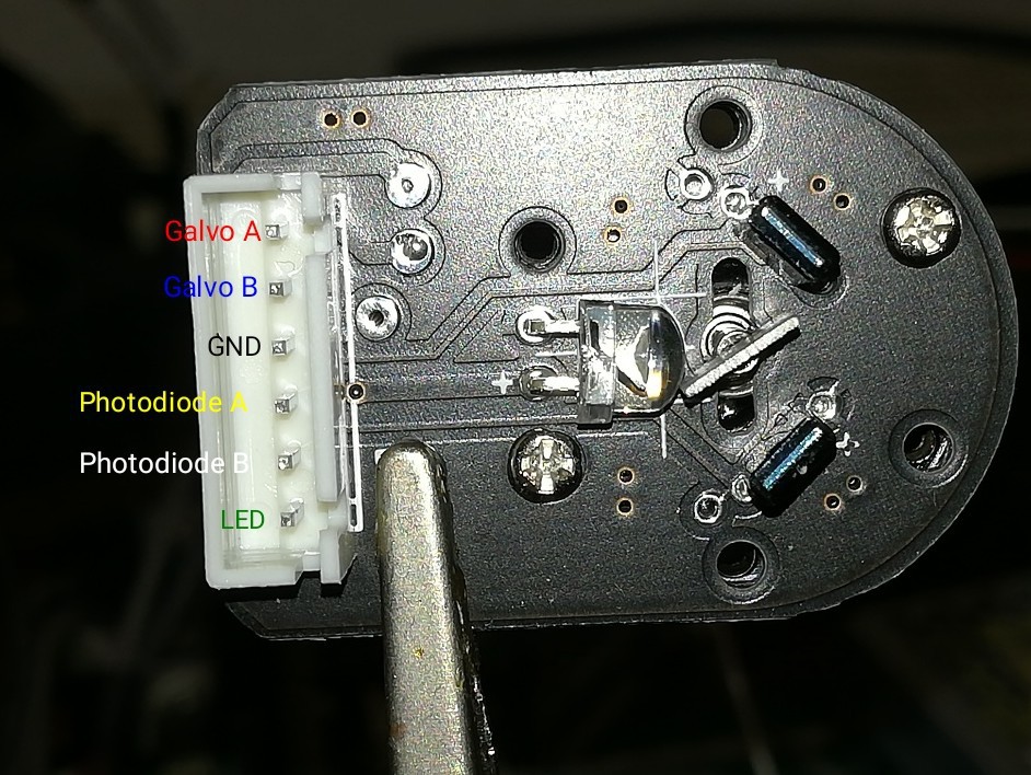
After removing the backside cover you can see an IR LED, two photodiodes and a small piece of sheet metal connected to the shaft of the galvo. Depending on the galvo's orientation and therefore the sheet metal's orientation the IR light hits more of one and less of the other photodiode which gives a quite precise position feedback.
![]()
I checked continuity and here is what I've got. Each of the photodiodes is connected to its own pin and to GND.
The next thing will be finding a way to create a control signal for the drivers.
Galvo Laser Cutter/Engraver
A GCODE compatible galvo laser cutter/engraver.