Of course, I needed some electronics to check the individual sensors and actuators from windiy. For this purpose I made a PCB design on which there should be space for all necessary components.
This PCb was made by PCBWay.com
In addition to the rectifier, the following functions are built into it:
Features:
• ESP32 powered
• Three-way bridge rectifier
• Step-down regulator
• Three independent charging circuits for one LiPo cell each
• Three I2C motor drivers to control the motors of the brake actuator and the pitch actuator
• various current and voltage sensors to measure the energy generated and consumed
• Connections for two Hall sensors for measuring the generator speed
• Connections for three sliding resistors to measure the positions of the pitch actuator and the brake cylinder
• Connections for two force sensors to measure the contact pressure of the brake cylinder
• Connections for four NTCs to measure the temperatures of the generator windings and the load resistance.
• Connection to be able to discharge the rectified voltage to a consumer
• Connection and electronics to be able to connect a load resistor PWM-controlled.
• Vibration sensor to detect abnormal vibrations
• two temperature sensors to monitor the temperatures on the PCB
• an electronic compass
• a micro-SD card slot
• A climate sensor for measuring the ambient temperature, humidity and air pressure
The board is of course still in prototype status. So it's no wonder that the circuit board didn't look the same after about a week
The board is of course still in prototype status. So it's no wonder that the circuit board didn't look the same after about a week
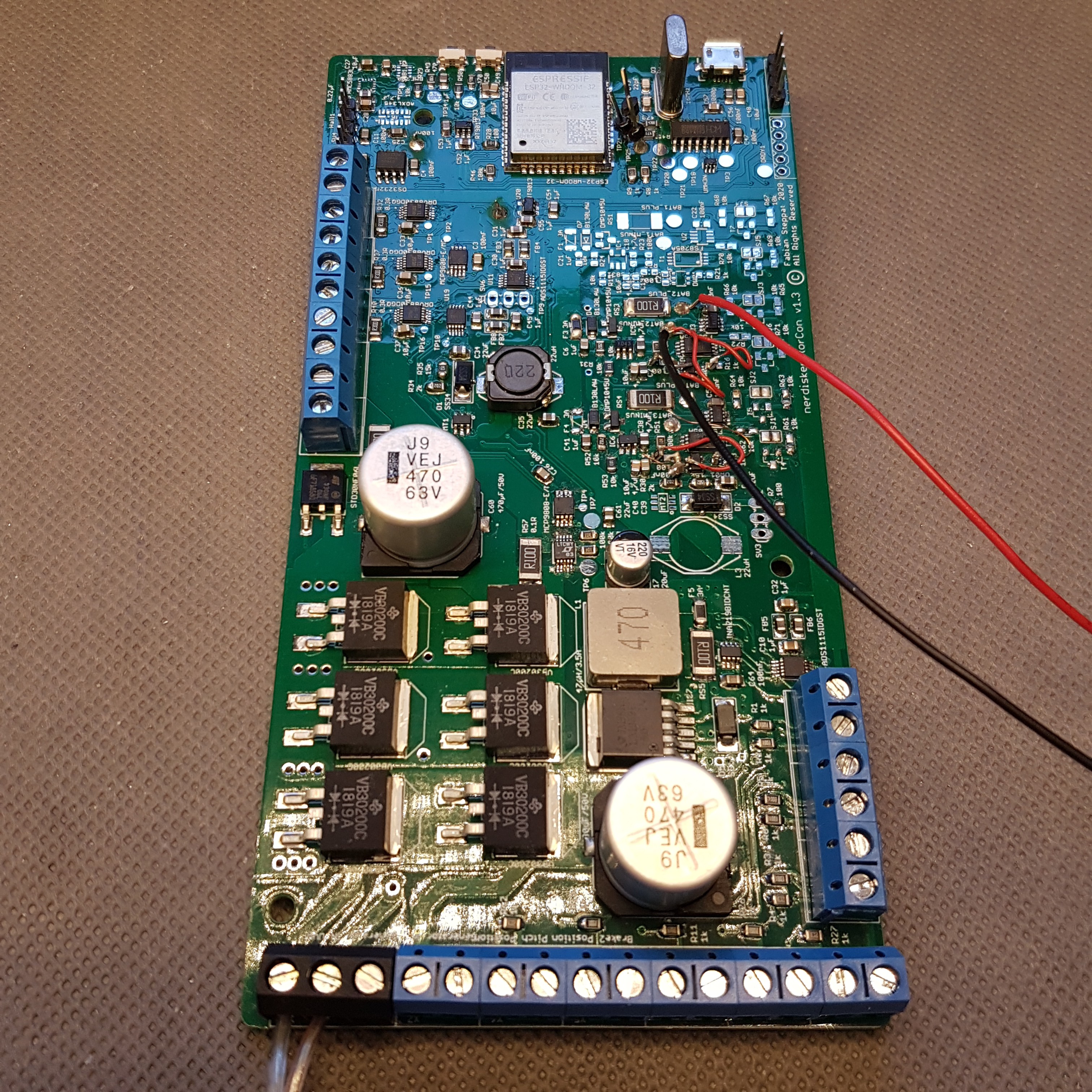
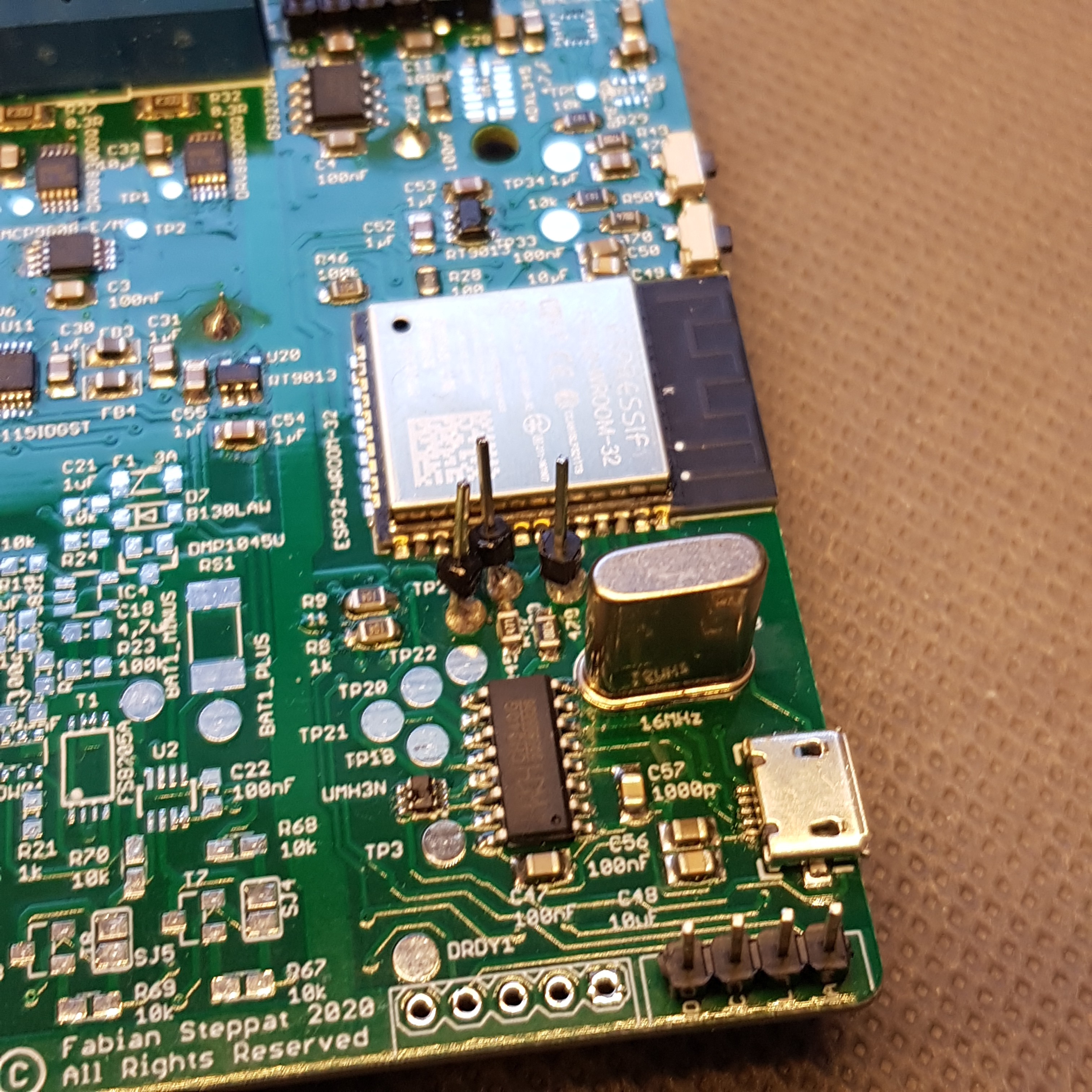
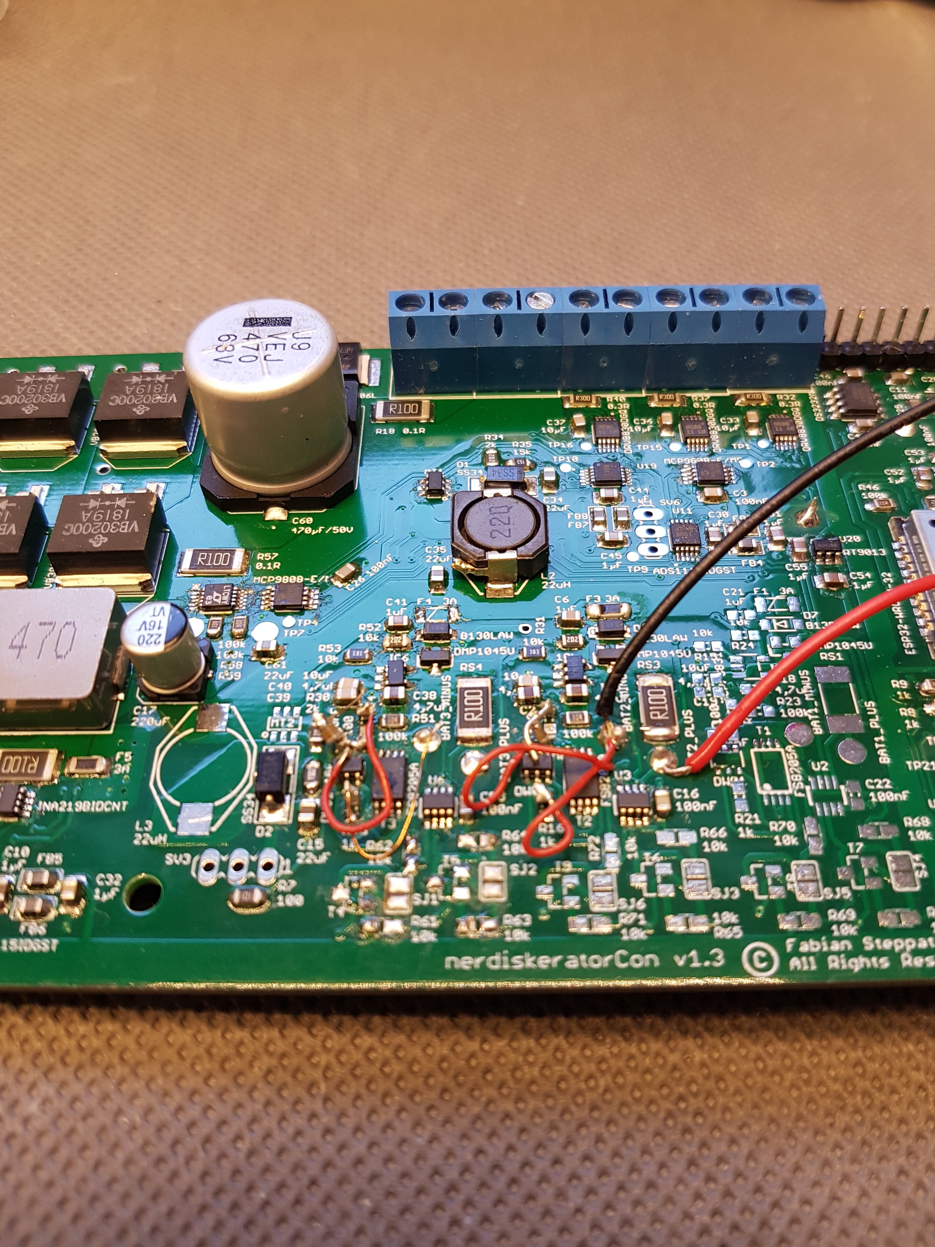
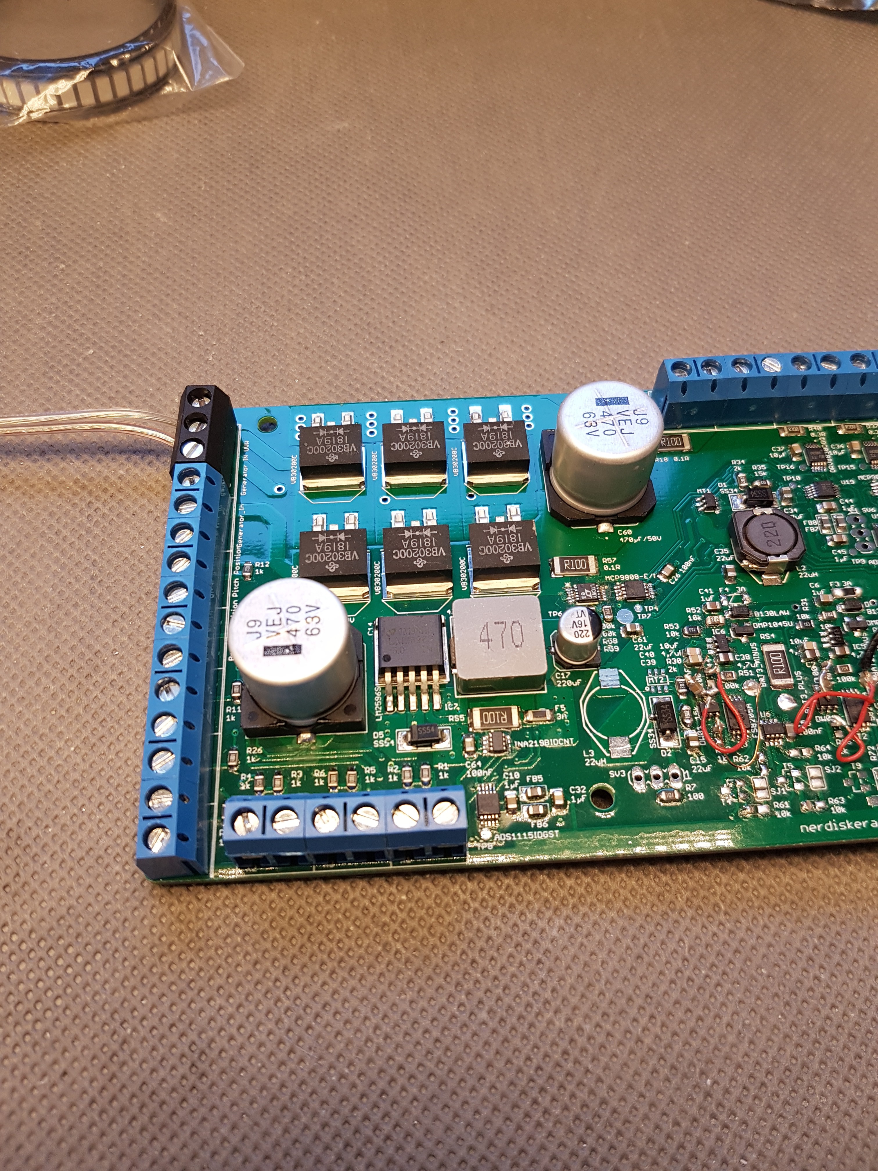
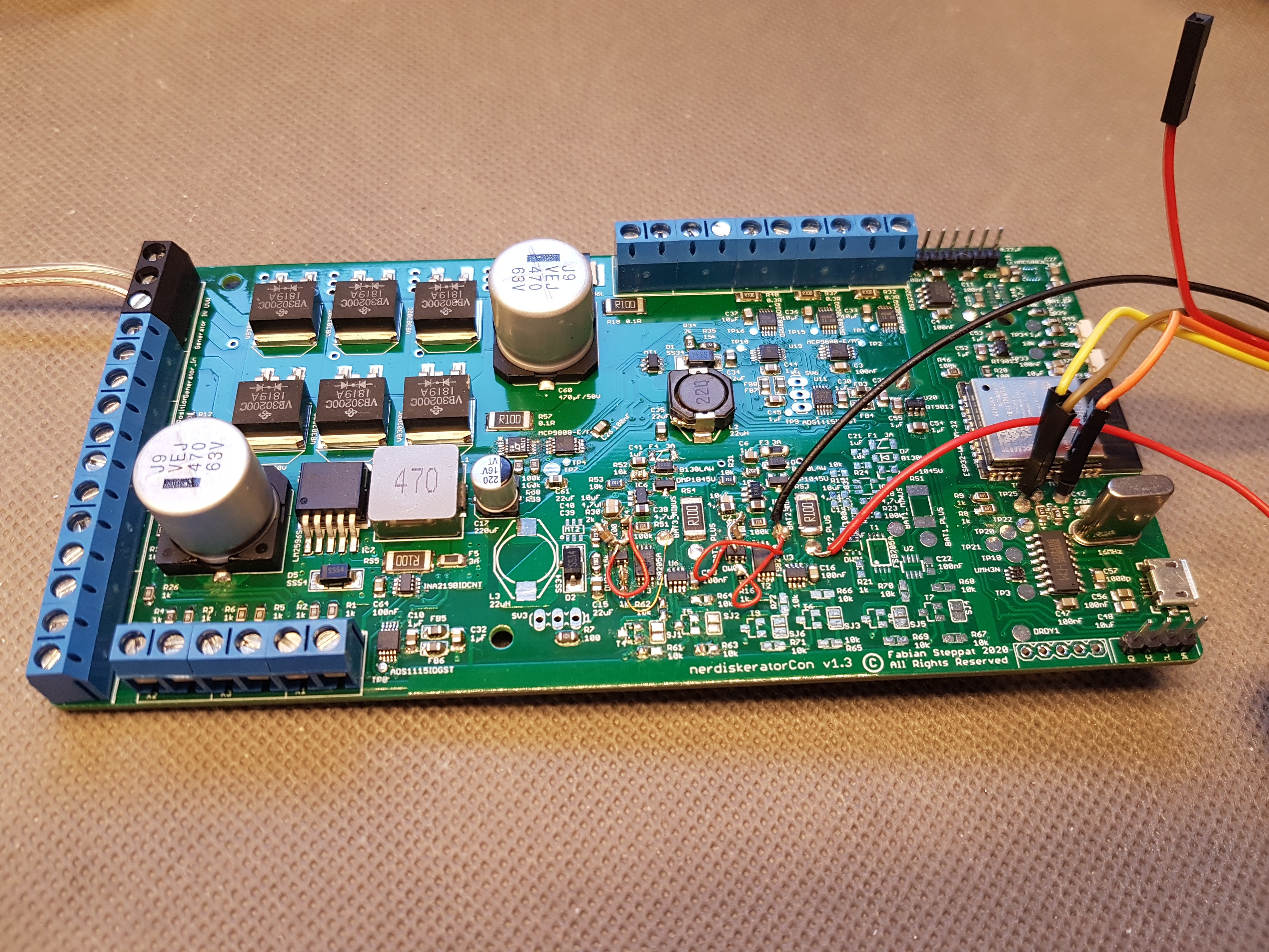
But like this:

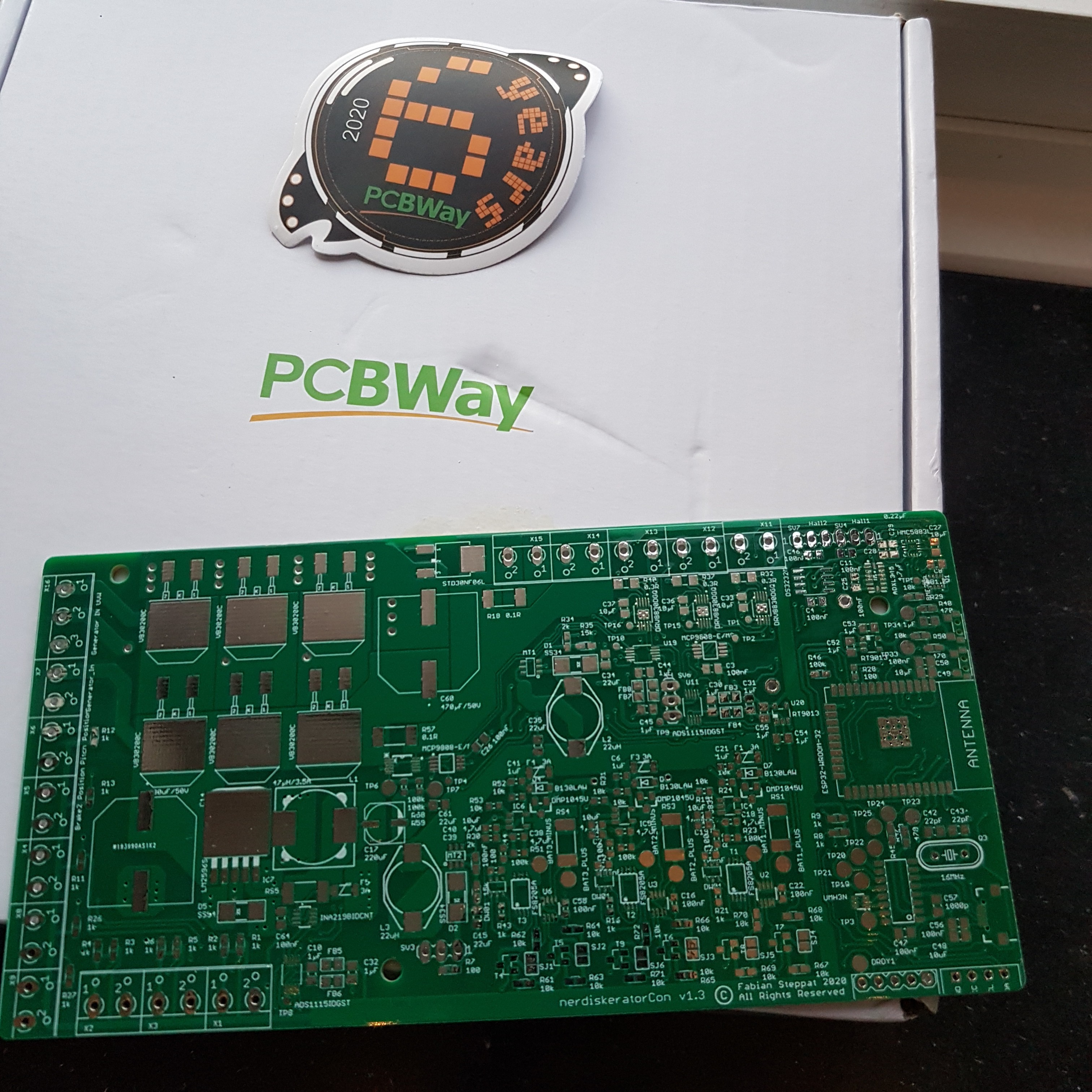
I uploaded a first version of the software here on GitHub: https://github.com/Nerdiyde/genCon
 Fabian
Discussions
Become a Hackaday.io Member
Create an account to leave a comment. Already have an account? Log In.