 Fabian
In the last few days, I have completed a first design for the actuator, which will be used to control the pitch/angle of attack of the wings.
Since I recently found some cool tools for designing gears (https://hackaday.io/project/172445/log/180101-test-stand-for-the-nerdiskerator) I was able to use them here too.
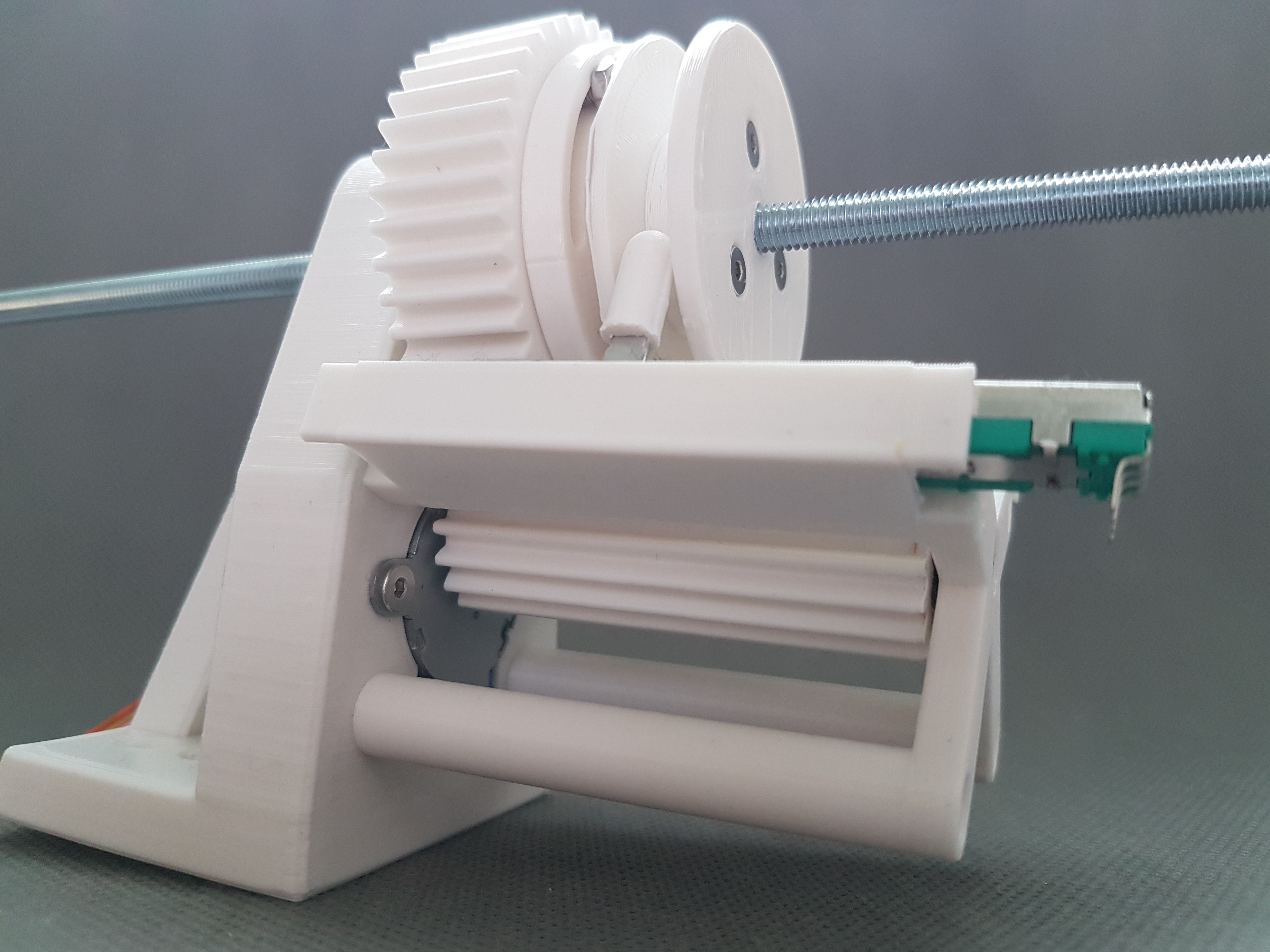
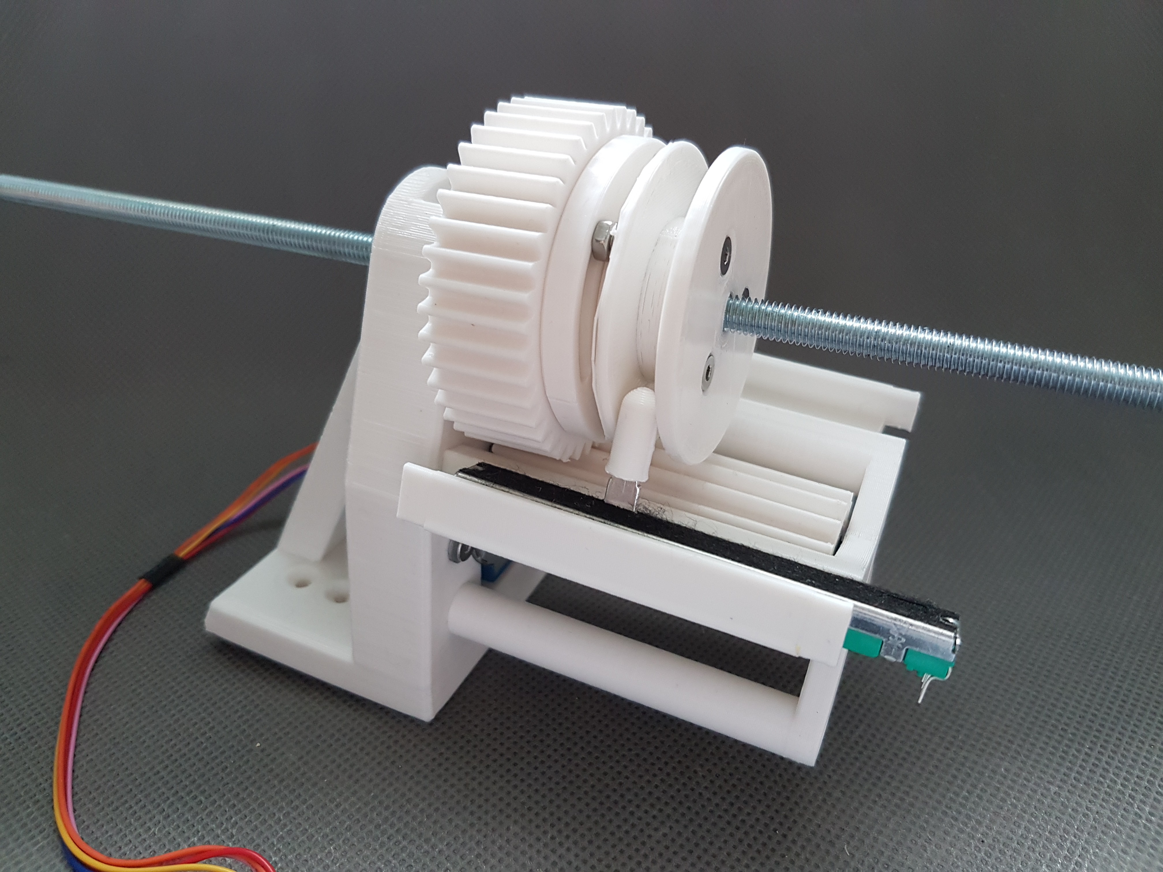
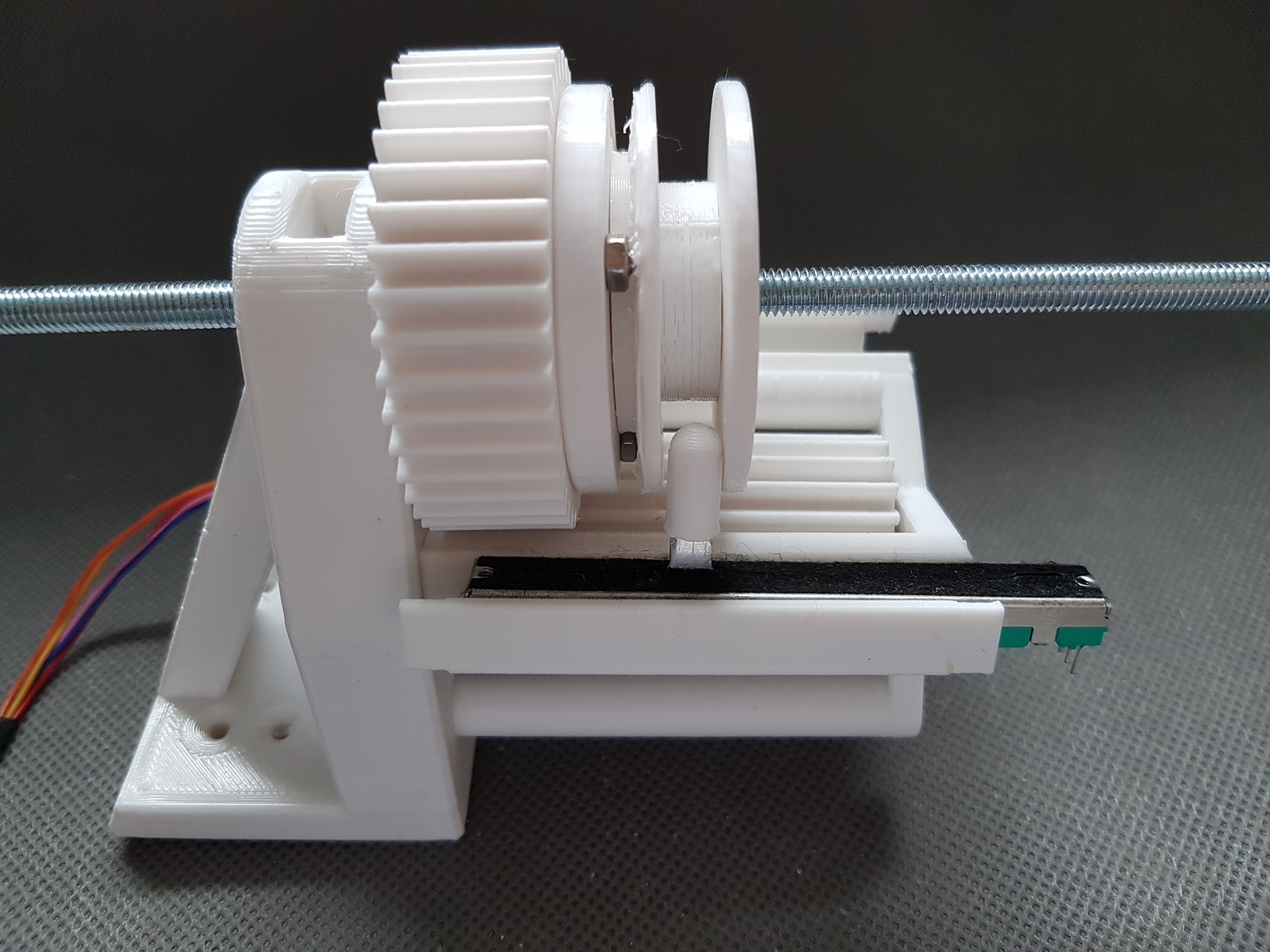
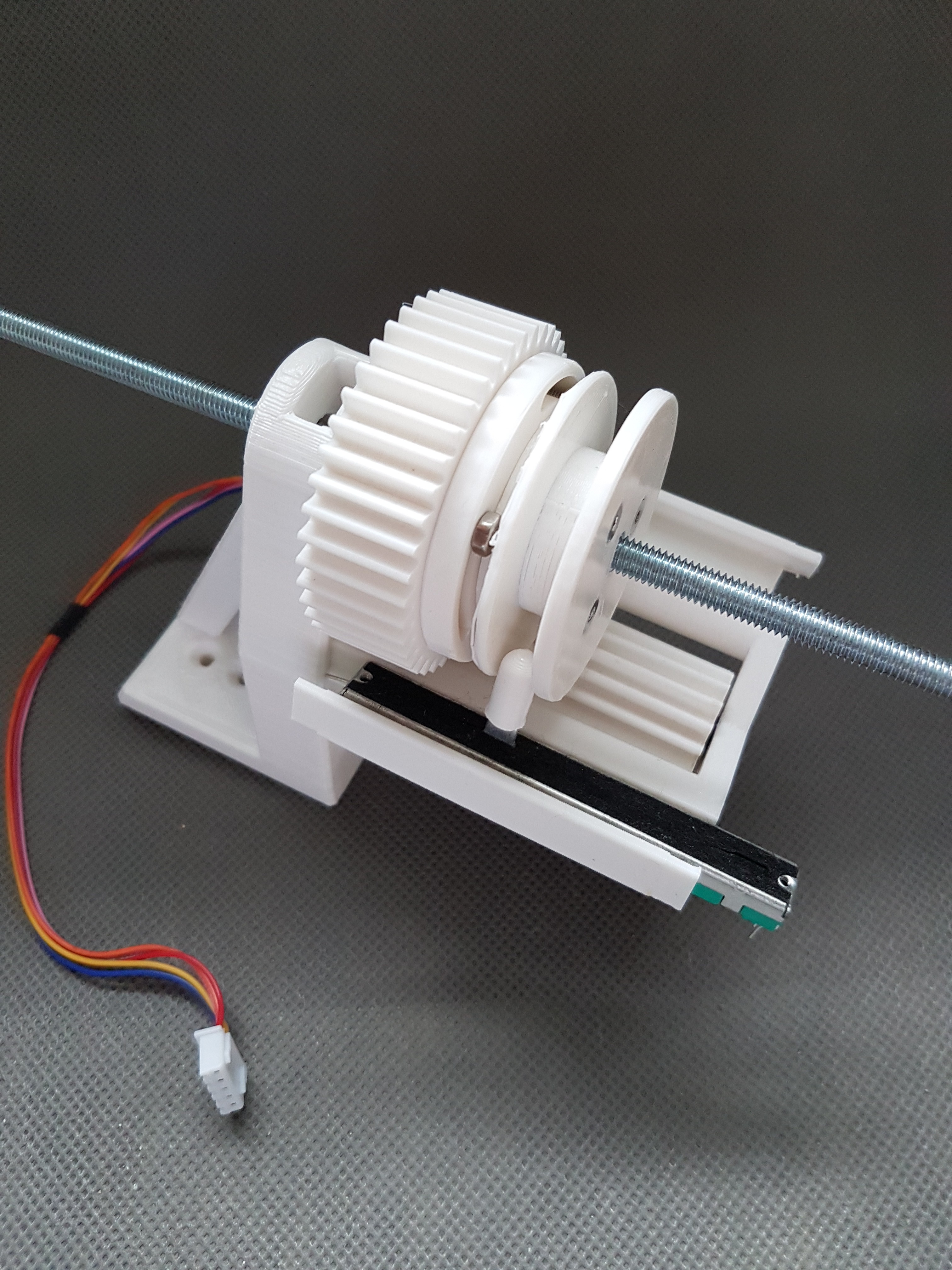
A small gear is mounted on the axis of the 28BYJ-48 stepper motor. This then drives the larger gear which is firmly seated on the M6 threaded rod.
Since the threaded rod is mounted in a nut, which in turn is permanently installed in the holder of the stepper motor, a rotation of the threaded rod will hopefully result in a forward or backward movement of the threaded rod.
Hopefully this should adjust the disc in the hub of the rotor and thus the pitch of the blades. :)
So that the current position of the M6 rod can be measured, I have installed a sliding resistor so that it is taken along by the back and forth movement of the gear/rod. So you would have to be able to use an ADC later to measure the position of the M6 rod.
Everything a little difficult to describe. So here are a few photos. As soon as I have a complete set up, I will also post a video. :)
Discussions
Become a Hackaday.io Member
Create an account to leave a comment. Already have an account? Log In.