 Noeël Moeskops
Arrival
I took a bit longer then I originally anticipated but I have finally received my PCB’s! The main reason it took so long was because I made some mistakes in the power board, I totally forgot to accumulate the characteristics of a capacitor at certain frequencies. But after reading my eyes dry at datasheets I managed to pick the proper parts and redesigned the layout a bit so it would all fit.
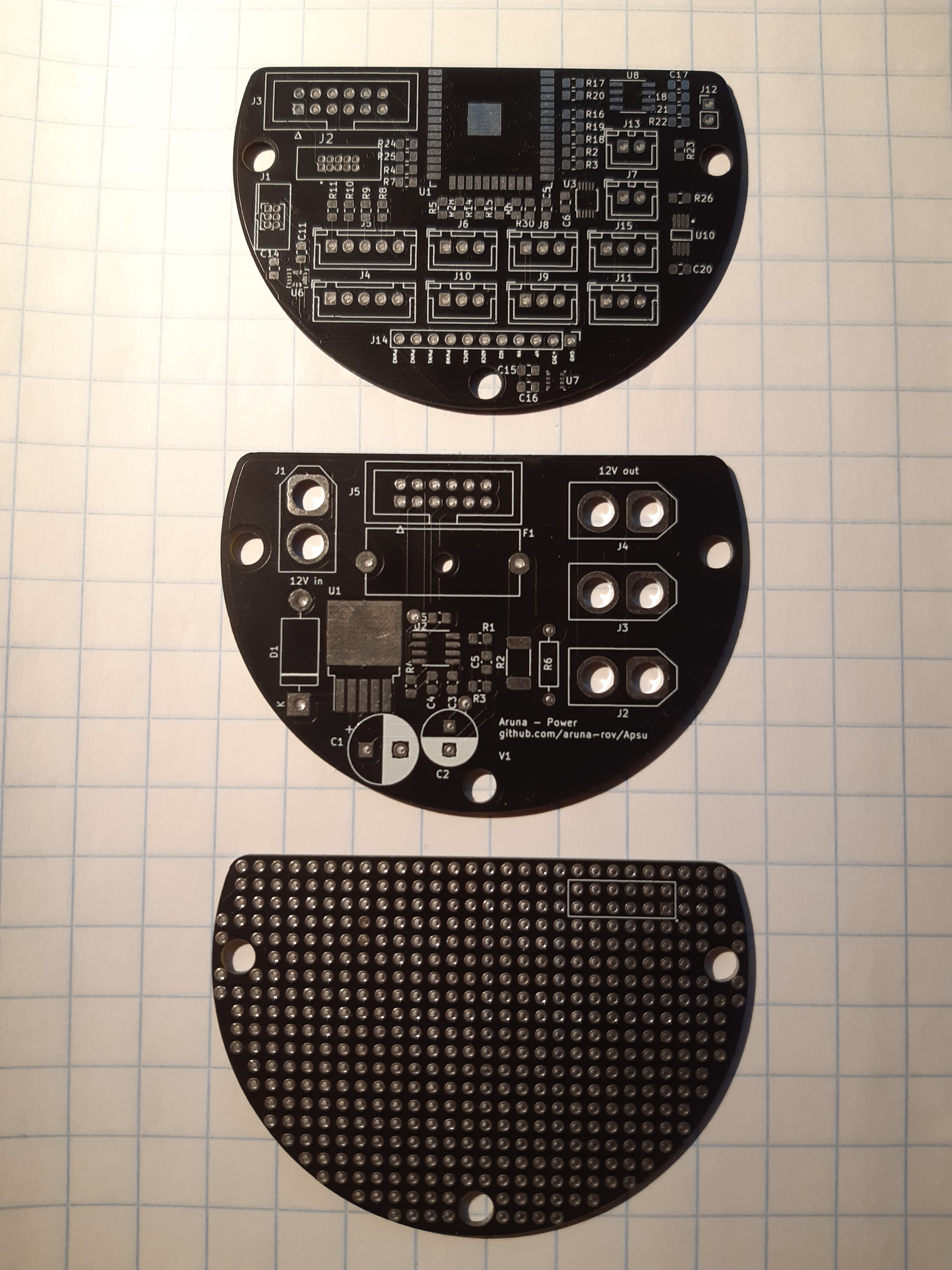

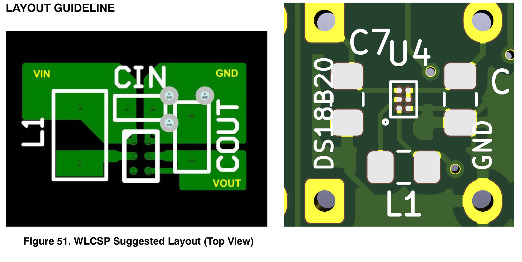
The three boards came out fine, the black matches with the rest of the ROV so it all looks pretty nice so far. This was my first experience with SMD soldering with a hot air reflow station (bought especially for this job) but non the less the soldering process went smooth, and there were little complications. During soldering, I noticed one big flaw in the main Apsu board through. “U4”, the boost converter on the back of board was mirrored. So I could not install the chip, pretty stupid mistake and I’m not sure how I managed it. I do recall a mental note on orientation of the IC but I missed it during checks regardless.
Testing
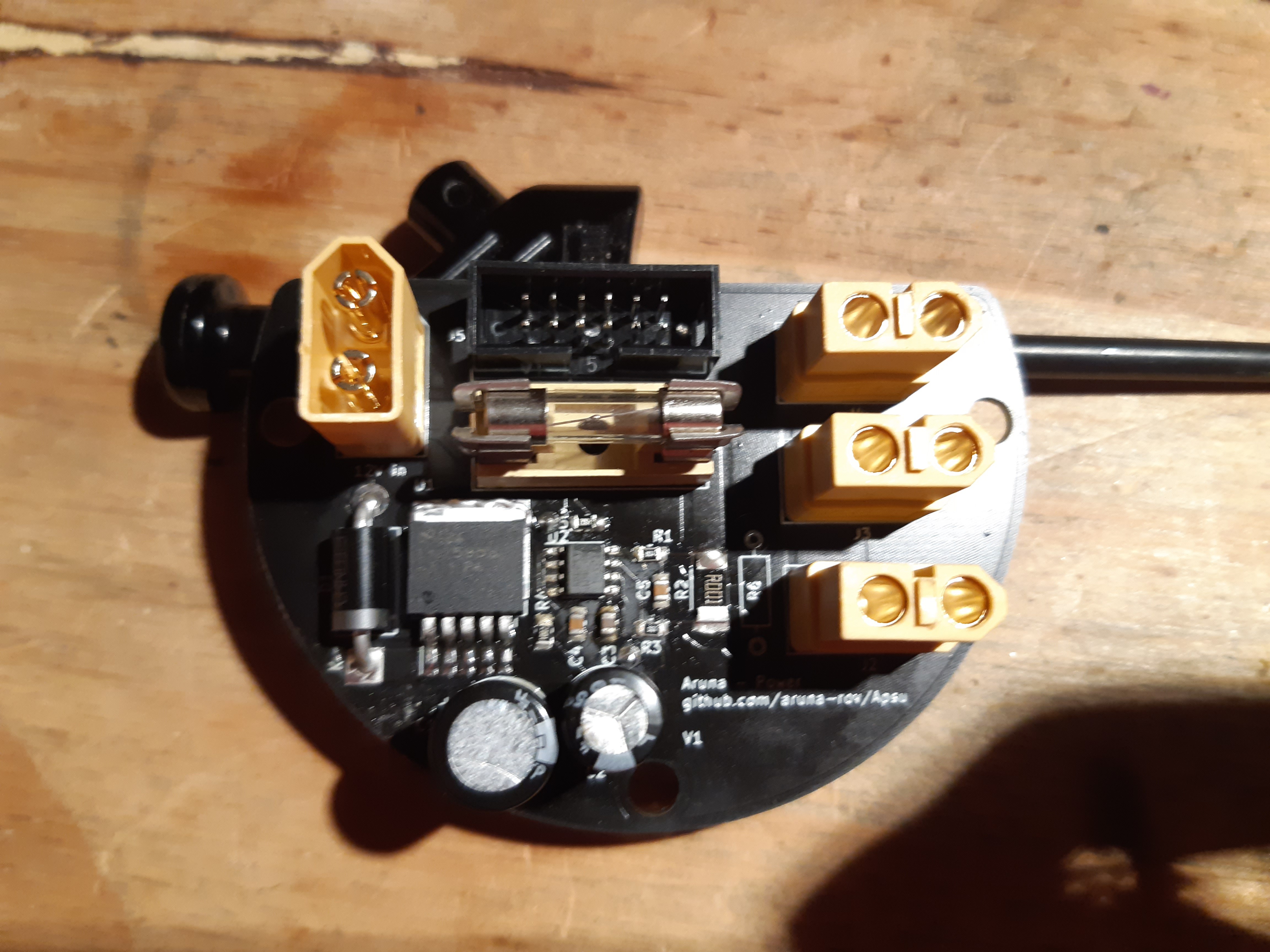
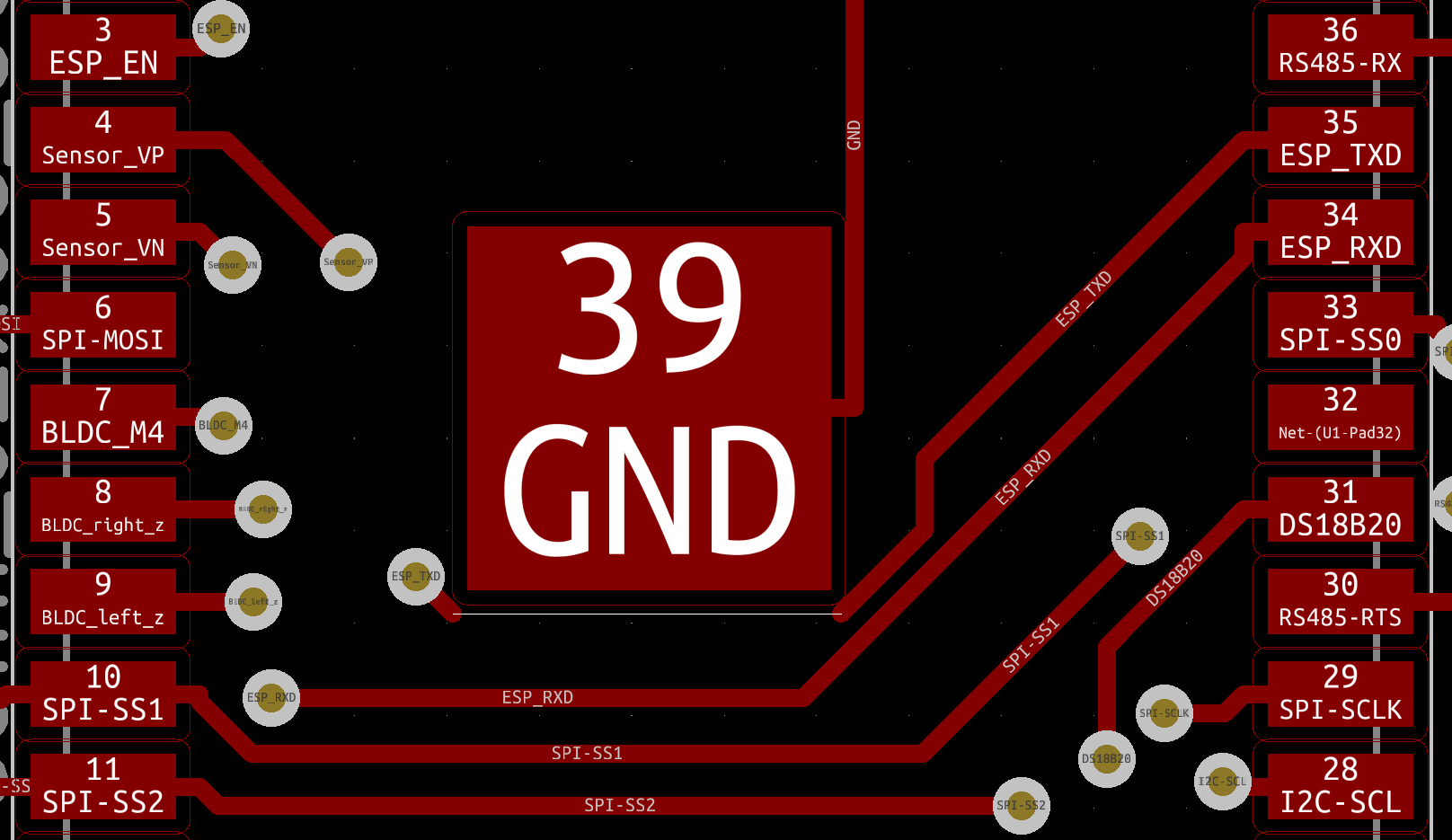
This is the moment of pay-off or regret. Whenever the months of research, designing and spending just short of 100 Euro on supplies was worth it. I first tried talking to the ESP32 module via JTAG and UART, JTAG worked fine and after flashing a hello world example program I was not receiving any data from the device. Stepping through the code using GDB showed that the code was indeed being executed but was somehow not getting to my computer. It turned out that the Tx track going under the ESP was missing from the PCB :(… Pretty big blunder if you ask me. Luckily I have learned from my mistake and will hopefully not make it again. I think it happened right after I was working on re-routing the Tx track and I then wanted to delete something while the Tx trace was still selected. Normally this would have been caught by the DRC check but that was giving so many false positives that I decided to ignore the whole report, haha. Soldering a wire to the two terminals fixed the issue, but the board does not look as elegant as it did before.
The power board produced a clear 3.3V signal so all my redesign work was worth it :), have not yet tested the volt/current sensor.
The MAX485 for RS-485 communication works, this was expected because I already created a failed attempt at a USB to RS-485 converter. So I learned from my mistakes. ADS1015 for 12 bit ADC through I²C works fine. And I’m currently in the process of creating a driver for it. The next IC I will test will be the PWM controller.
Discussions
Become a Hackaday.io Member
Create an account to leave a comment. Already have an account? Log In.