Dr. Cockroach
-
Coming out of hibernation
12/06/2020 at 01:14 • 0 commentsDecember 5, 2020 - I have been working on other projects for a while and let the LLTP take a bit of a deep sleep. It is just about time to warm up the iron and wake this project up once again :-)
-
Yet Another Register
09/24/2020 at 23:58 • 0 commentsSeptember 24, 2020 - Yet another register about to be born. Number three in this case.

-
Program Counter
09/15/2020 at 15:16 • 0 commentsSeptember 16, 2020 - First test of the Program Counter. Slow but steady....
Sept 15, 2020 - Getting started on the Program Counter register and hope to start some basic counting in the next day. Wish me luck ;-)
The above is just one bit of the PC register and below is just before adding the diodes and logic wiring.
-
Mid September state of the LLTP
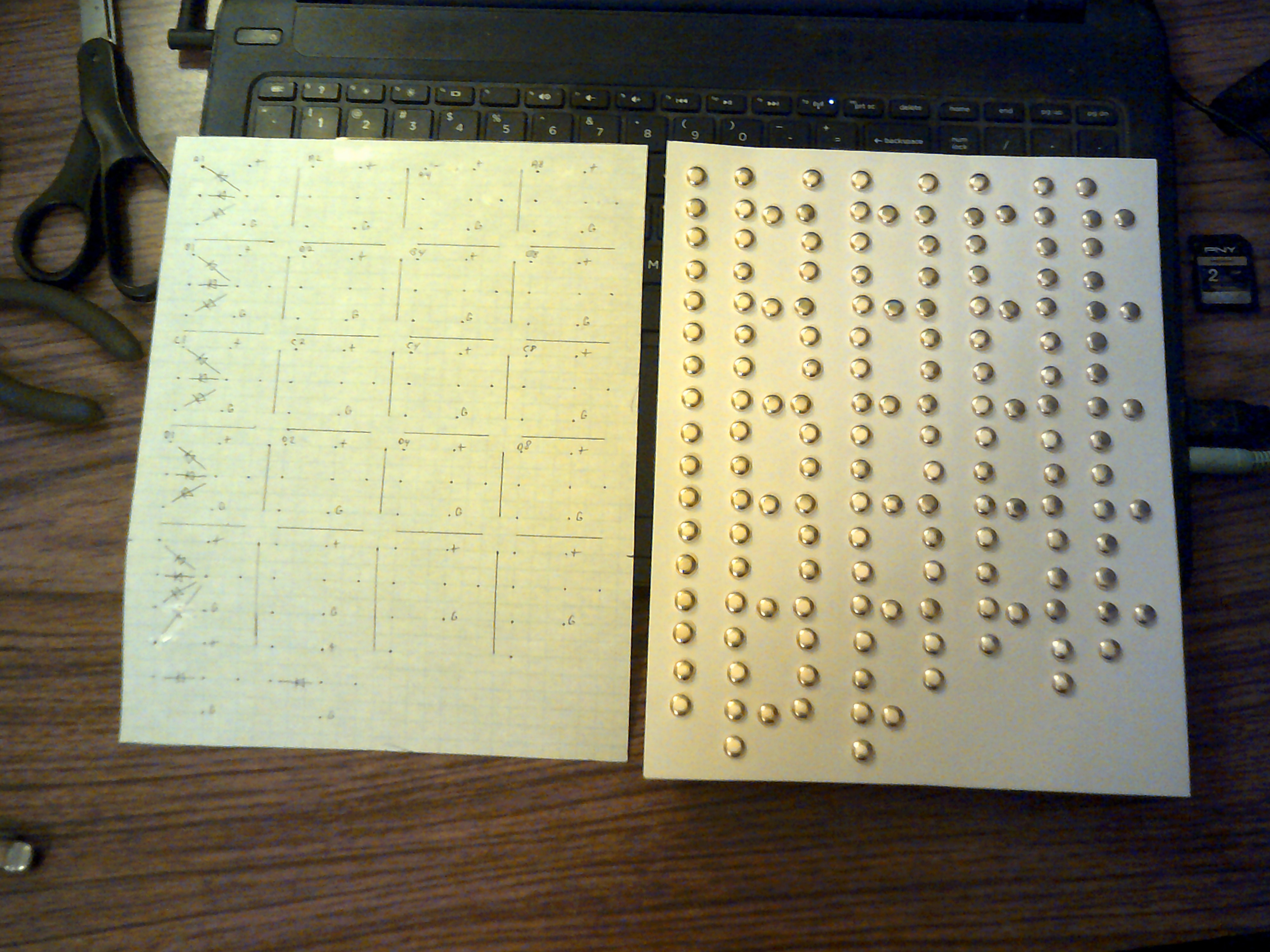
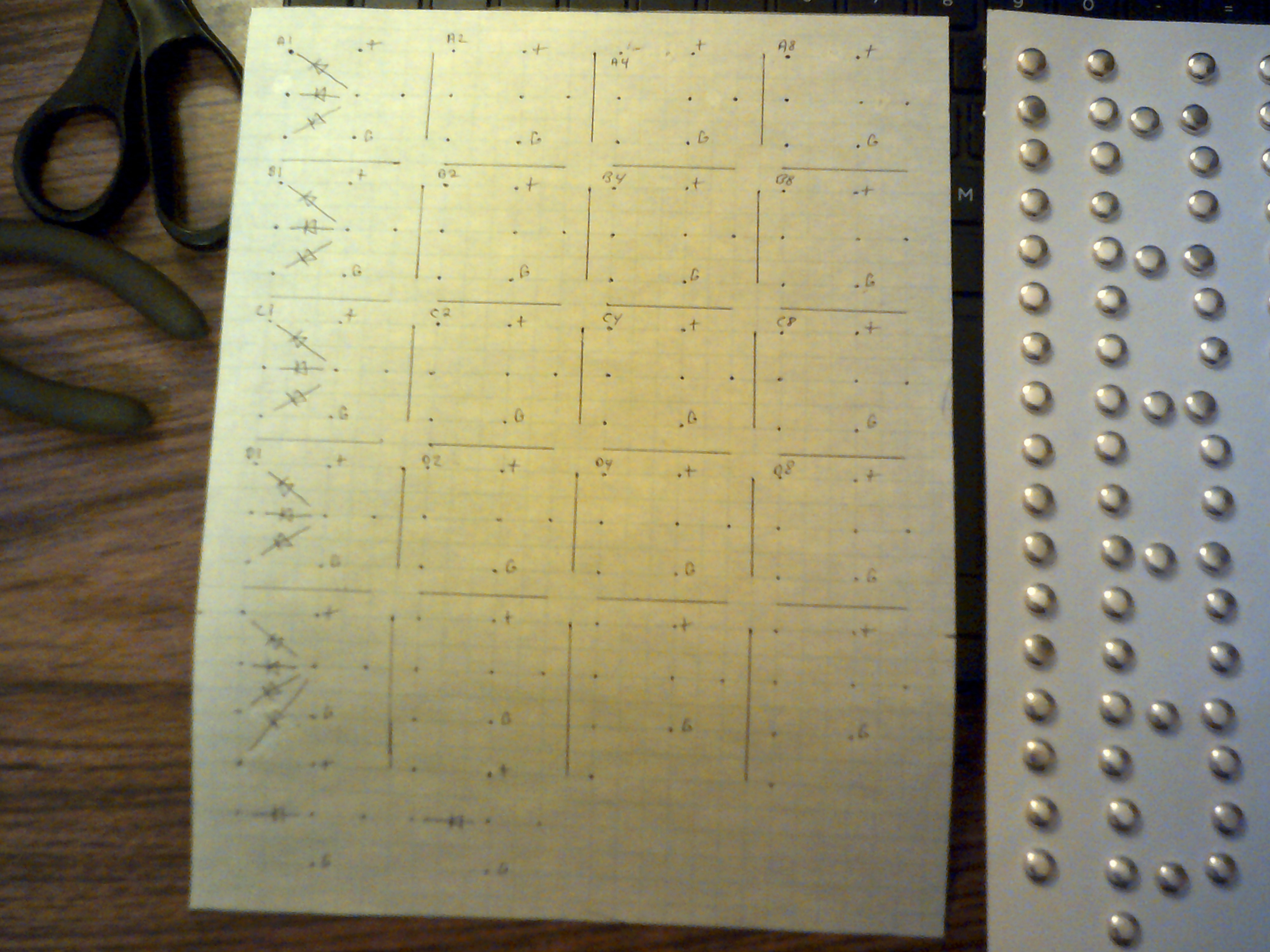
09/13/2020 at 16:56 • 0 commentsSeptember 19, 2020 - I decided that I need to start adding labels to the LLTP to indicate what is what. Even I will get confused later as I add more registers.
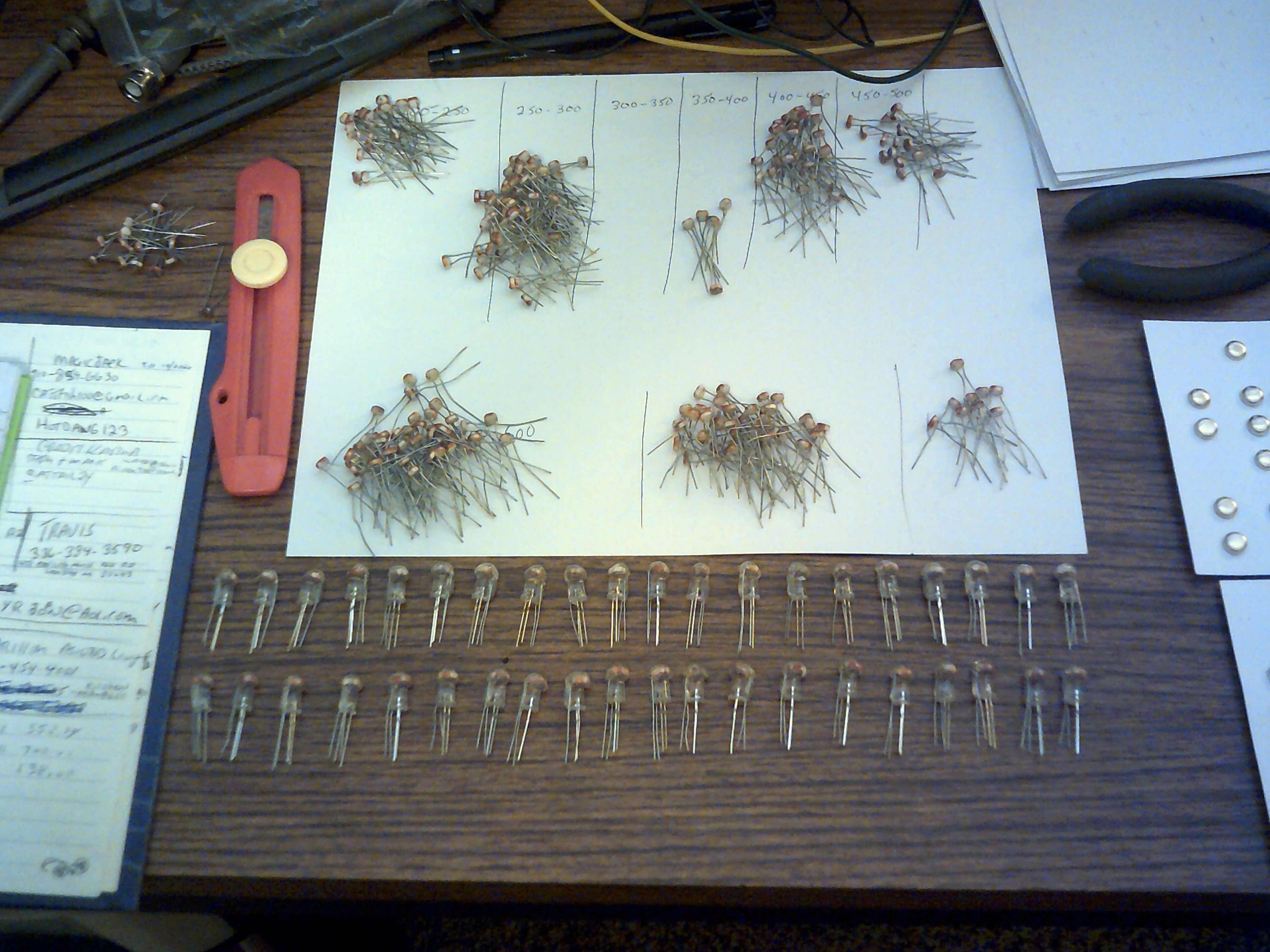
September 14, 2020 - Just a brief update of where I am with the LLTP project. I am currently matching up CdS photo resistors and making a batch of 80 Light Logic opto-couplers and those will be used to wire up four 4 bit registers. These will be used for the Program Counter, Instruction Register and the A and B input Registers for the Adder.That's enough couplers for two 4 bit registers.
-
Instruction Decoding
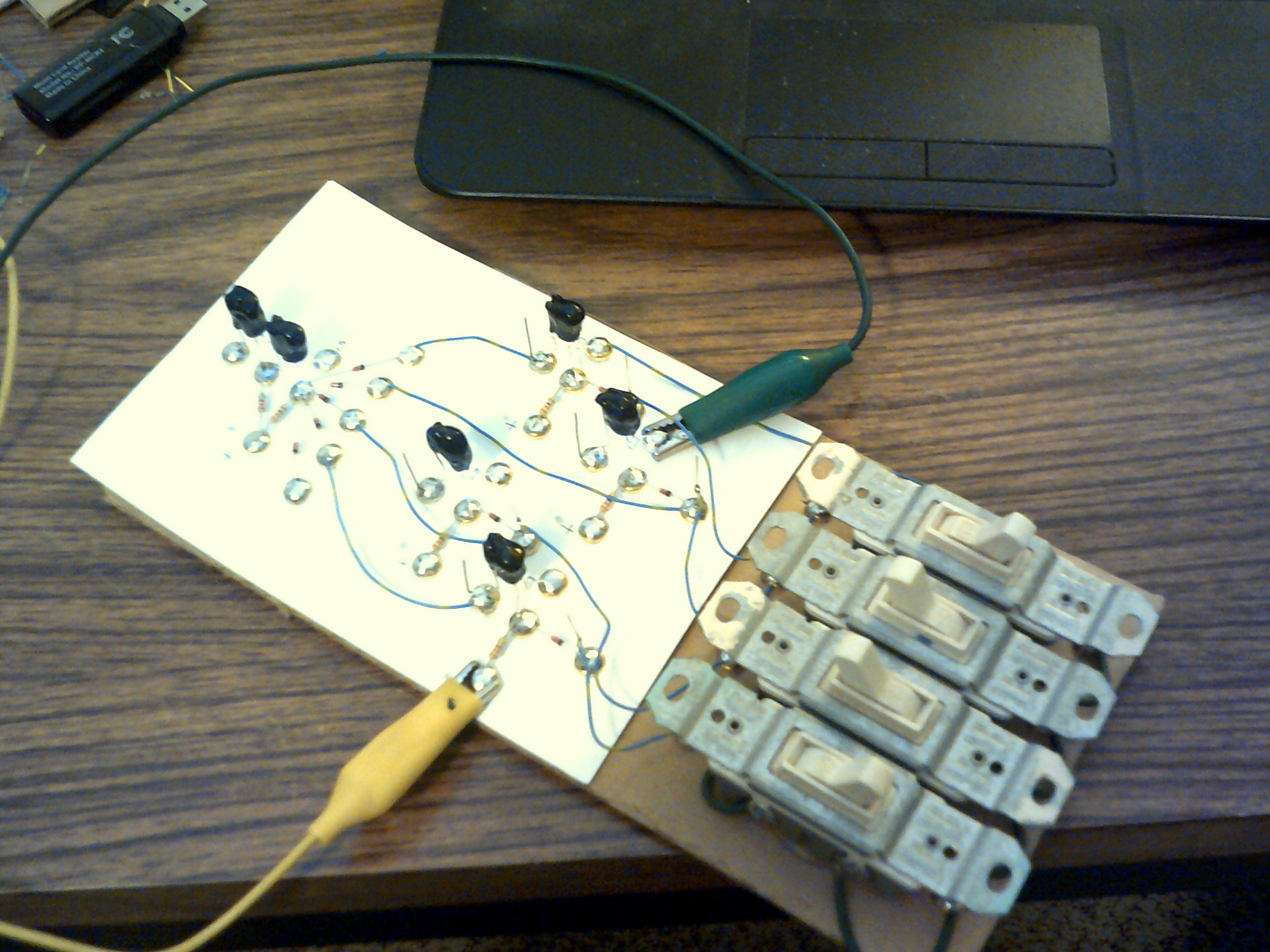
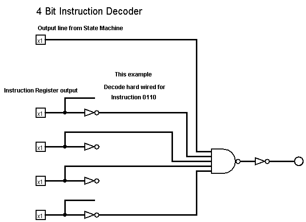
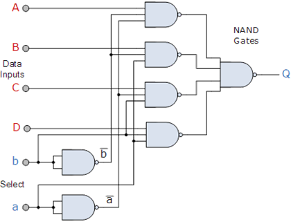
09/09/2020 at 22:40 • 0 commentsSeptember 9, 2020 - Just now finished wiring up and testing a basic instruction decoder. I am using 4 switches to simulate the instruction register at the moment but will swap those out for the real register soon. The picture shows a 0110 as the simulated instruction and with this 4 bit number fed to the hard wired decoder it will pass the signal from the selected State Machine output and proceed with the instruction logic.
-
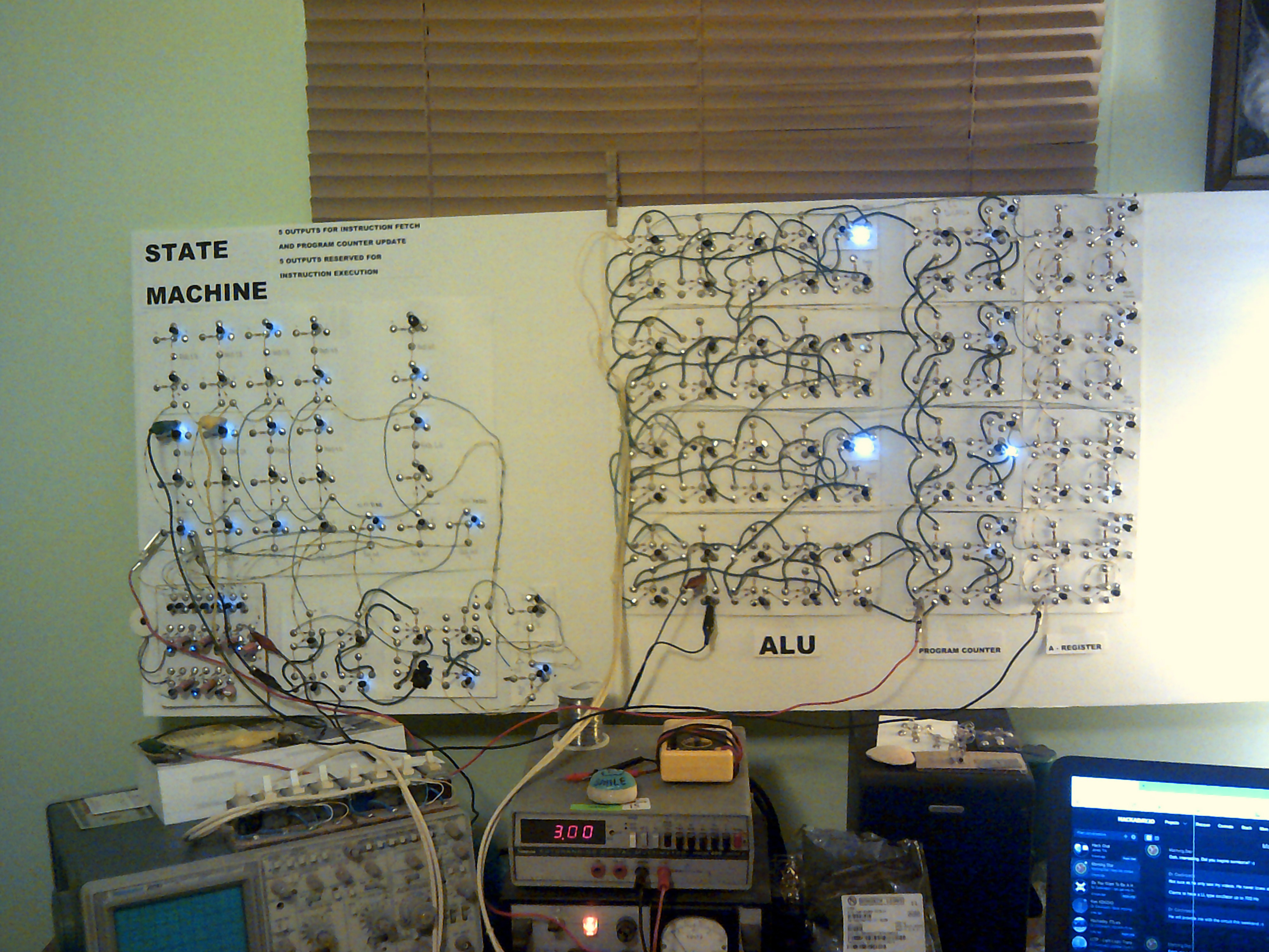
The State Machine
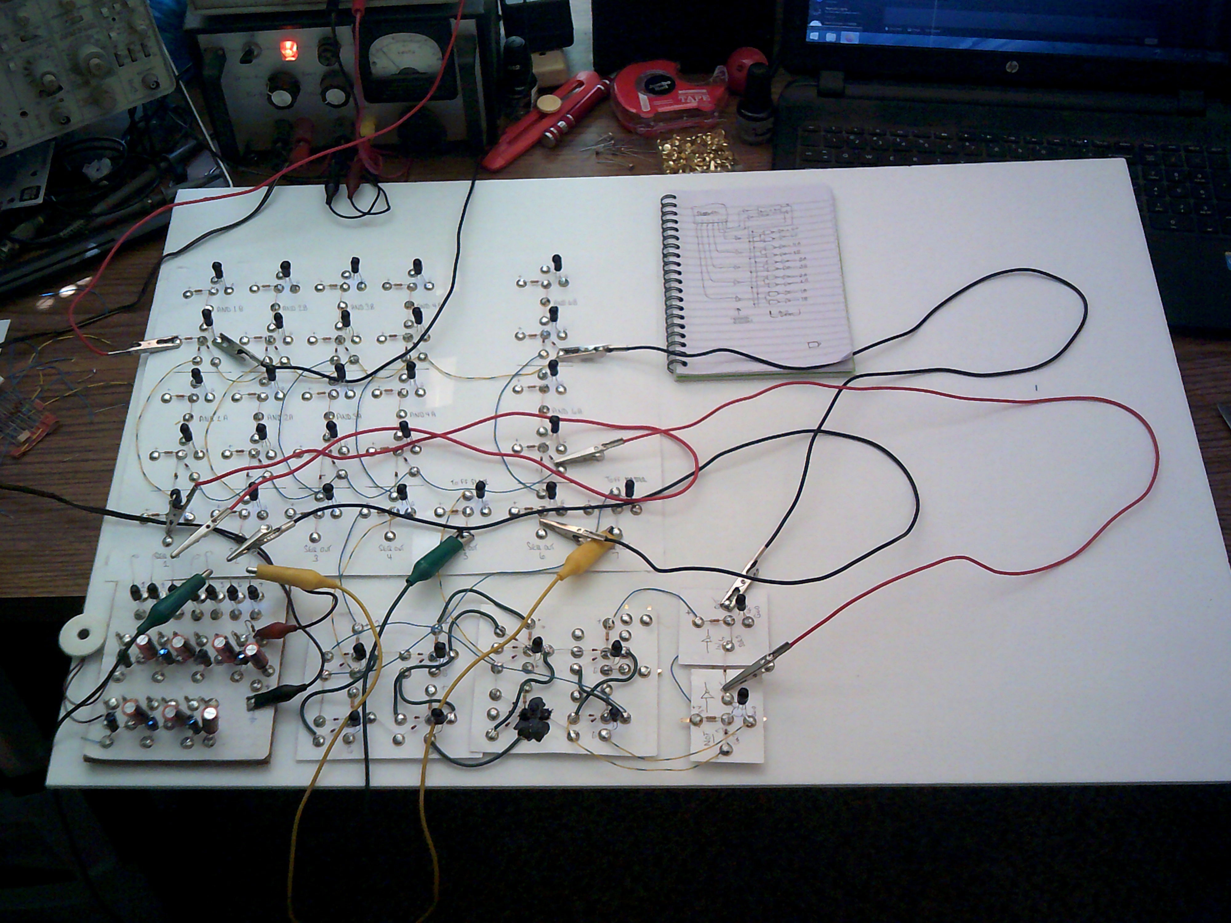
09/02/2020 at 15:16 • 0 commentsSeptember 4, 2020 - The transistorless State Machine is coming along and is going through the debug stage. It has a few glitches but generally is performing the way I want it to. The short video clip shows the cycling action taking place between the sequencer, flip-flop and the main logic.
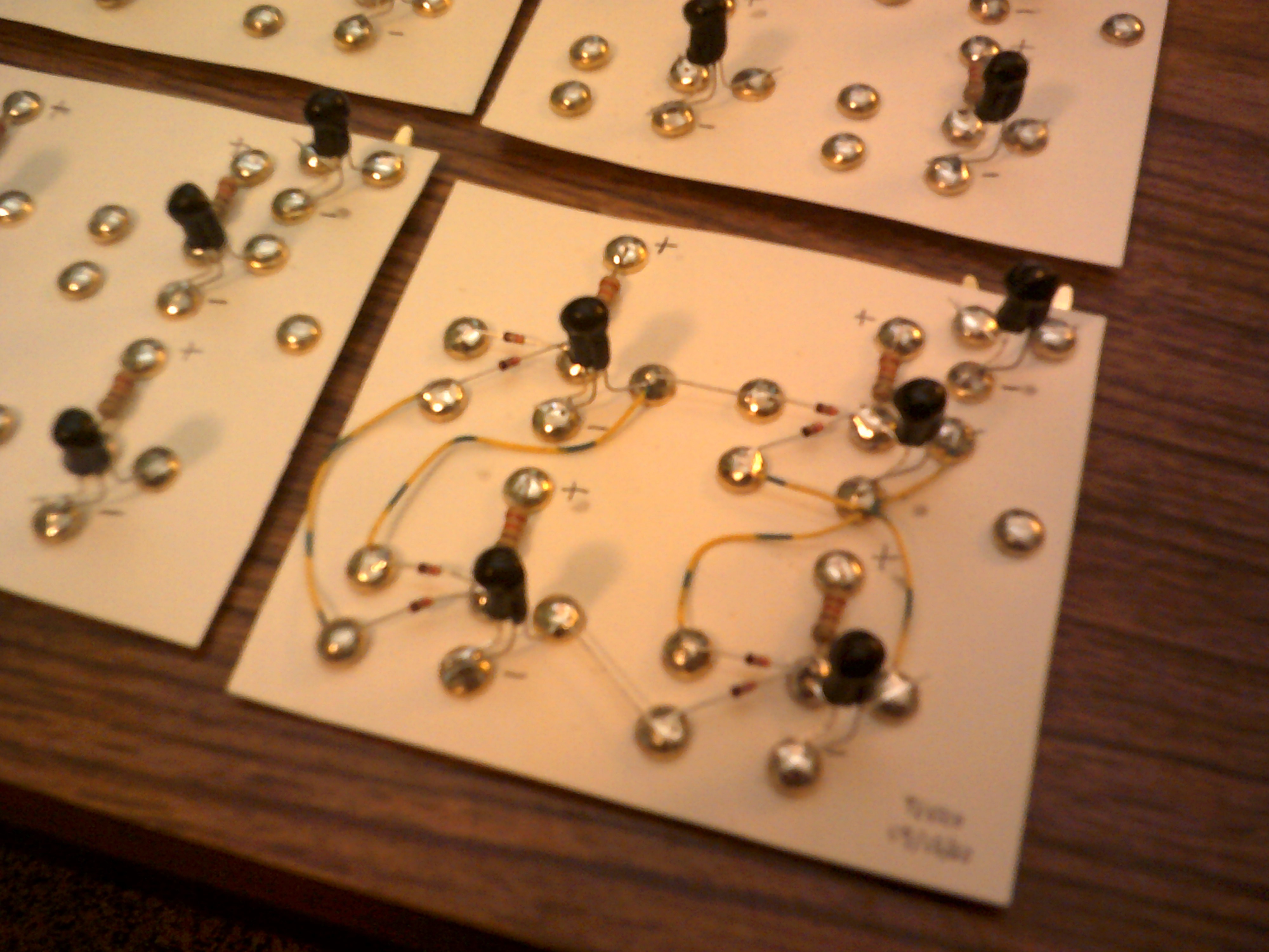
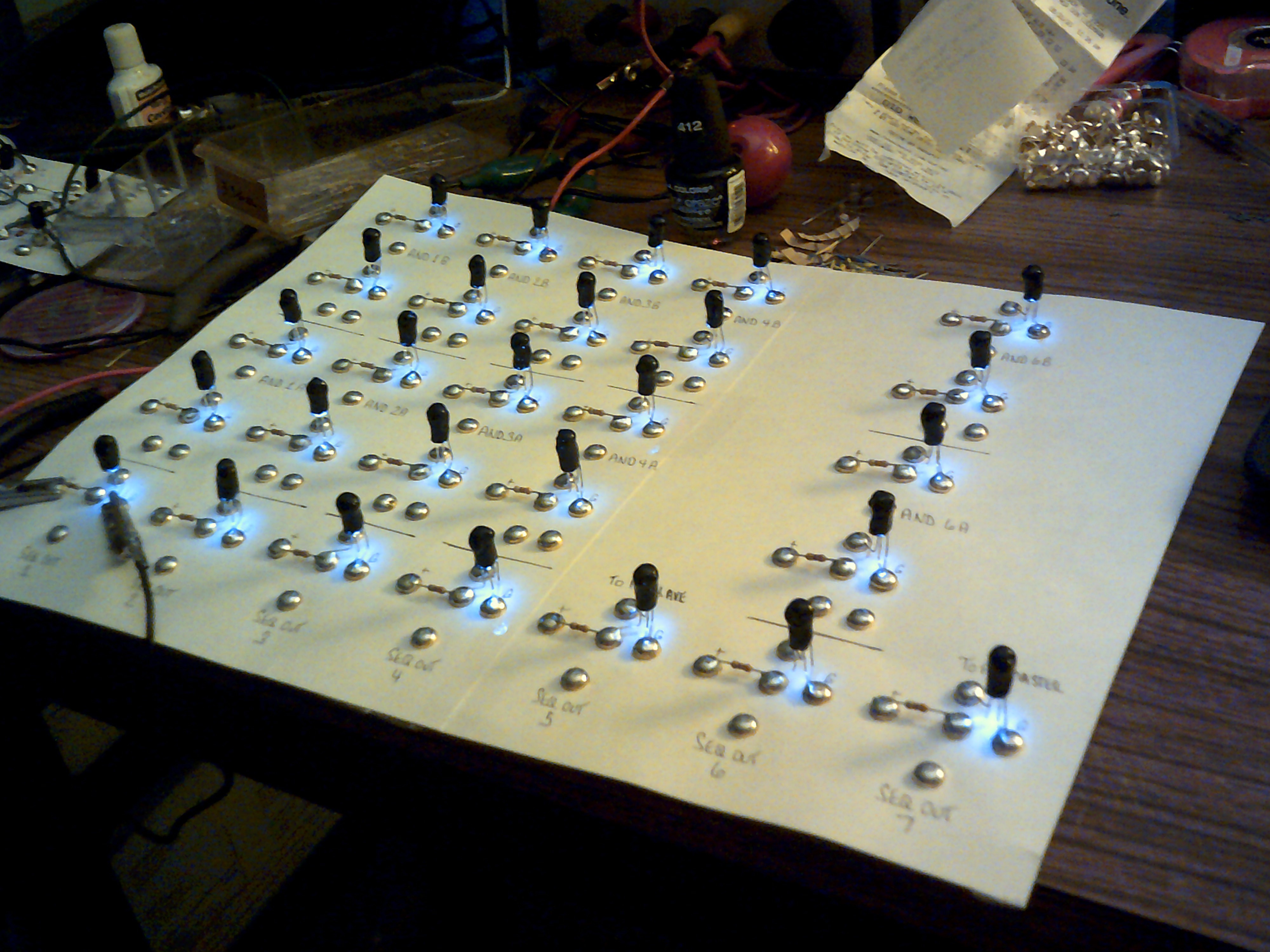
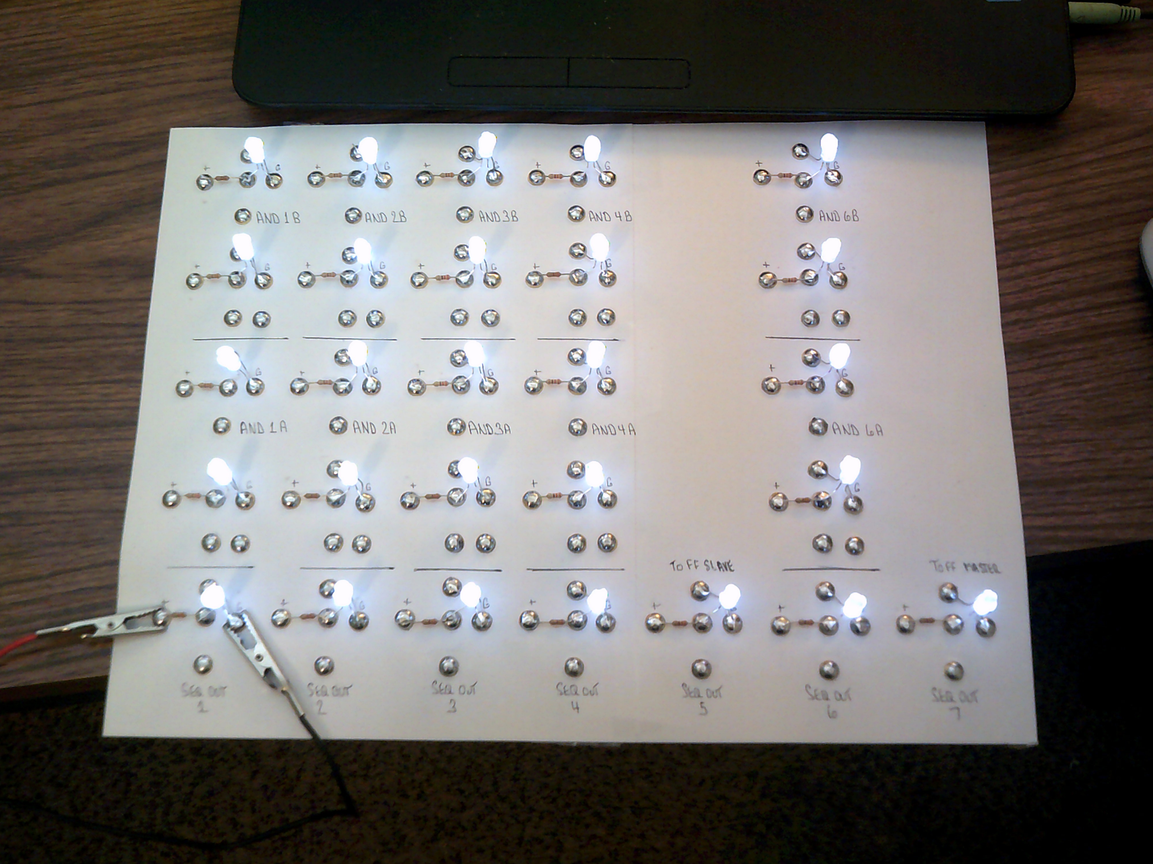
September 2, 2020 - This construction is the large part of the State Machine. This logic board along with the previous Flip Flop performs the switching that almost doubles the Sequencer outputs. This odd design will all become a bit more clear once it is up and running.
At this point all the Light Logic opto-coupler cells have been coated in black nail polish except for the bases. That leaves a nice glow when the gates are active once the logic wiring is finished.
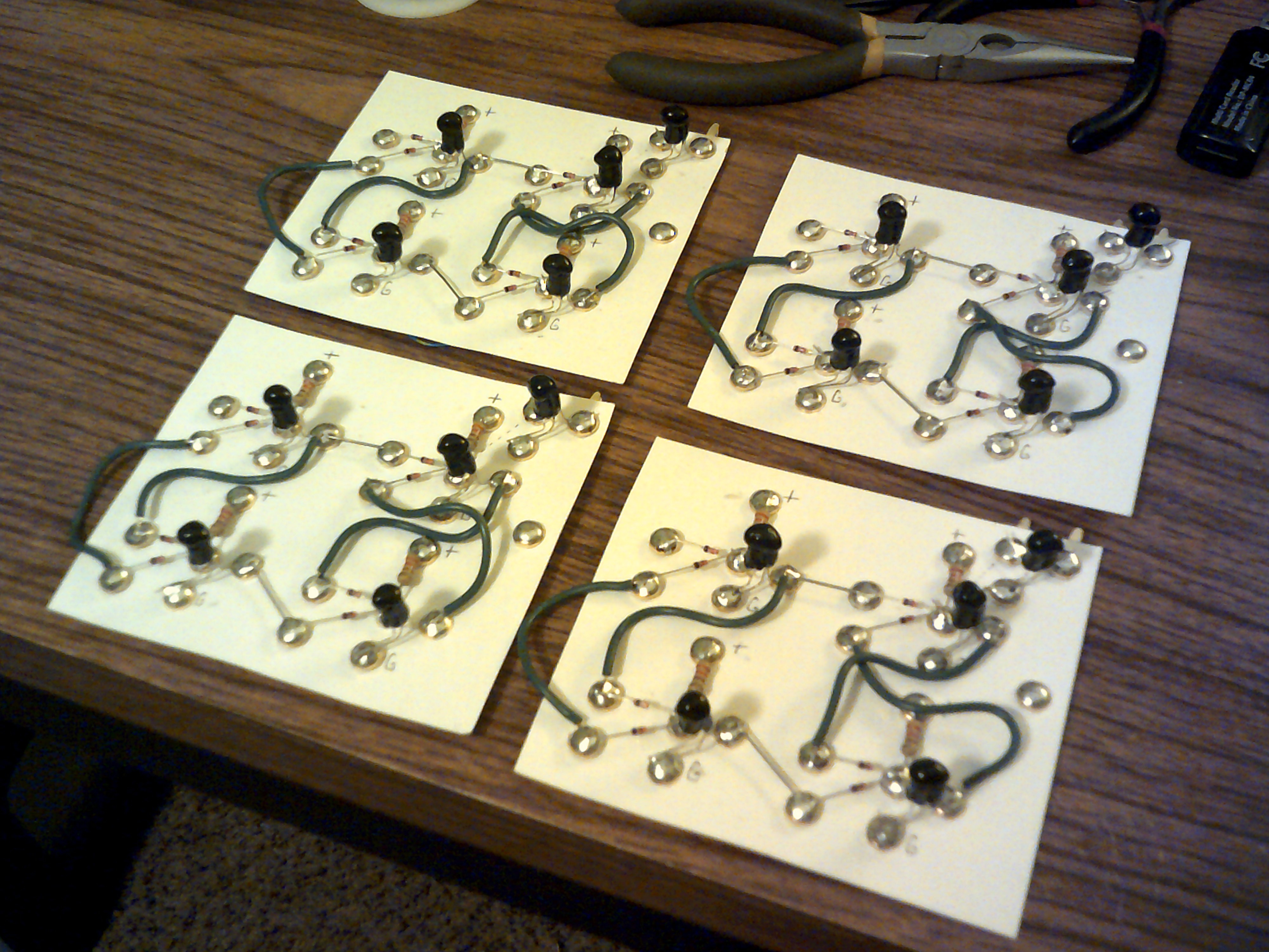
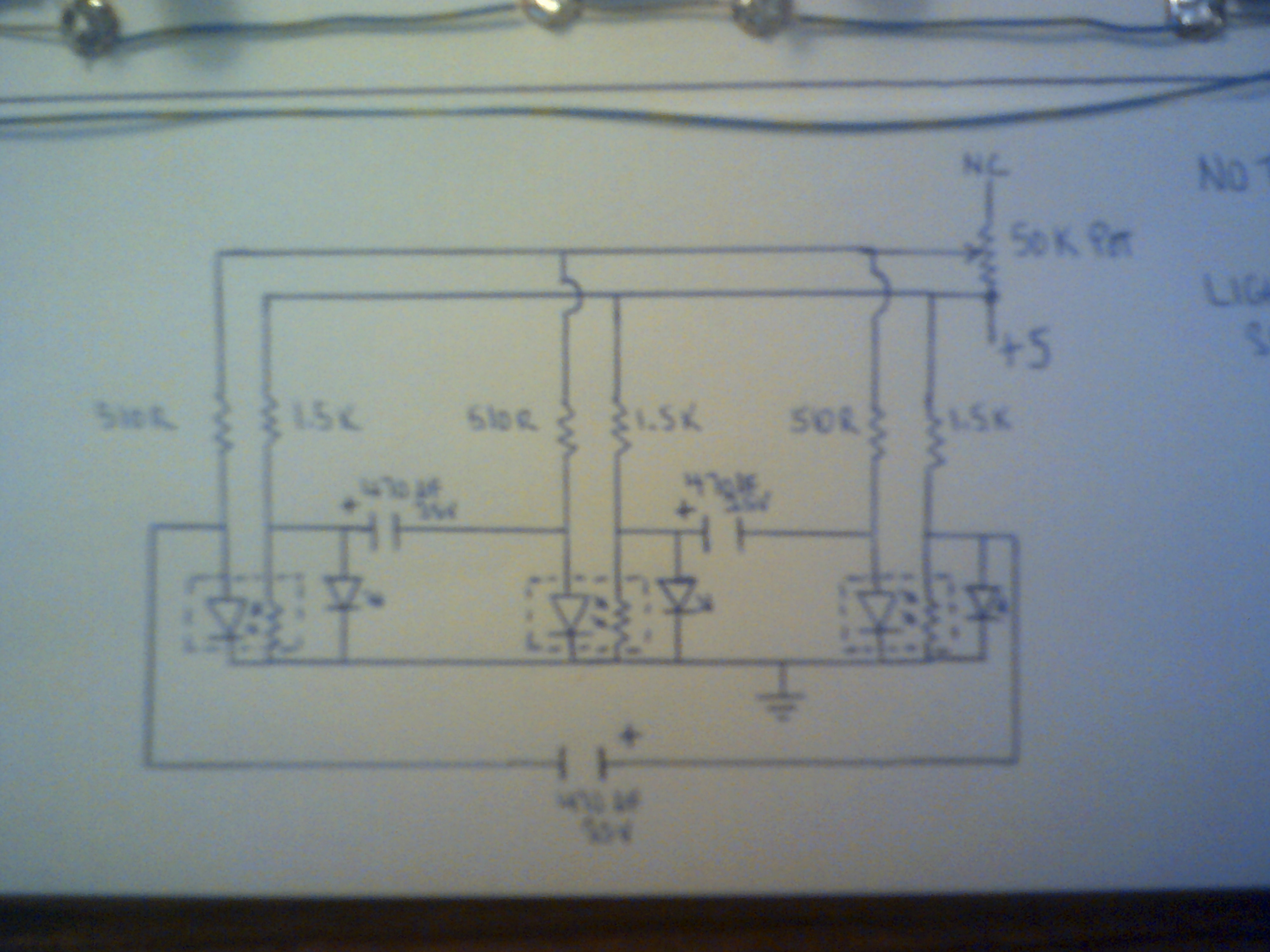
330 Ohm resistors are installed and 3 volts applied to the power buss. Rechecked that the CdS cell minimum resistances were still in the usable range between 200 and 450 ohms.
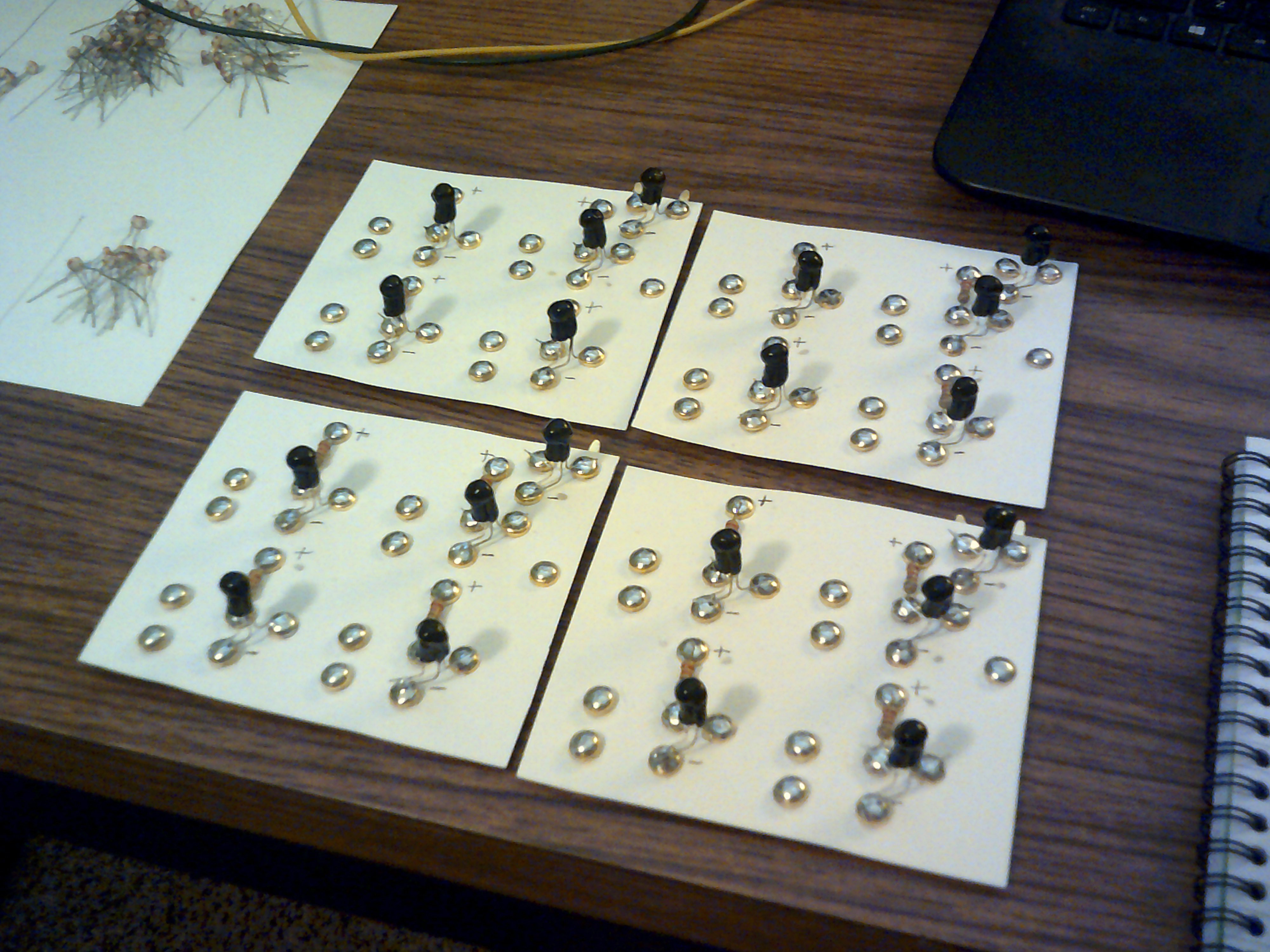
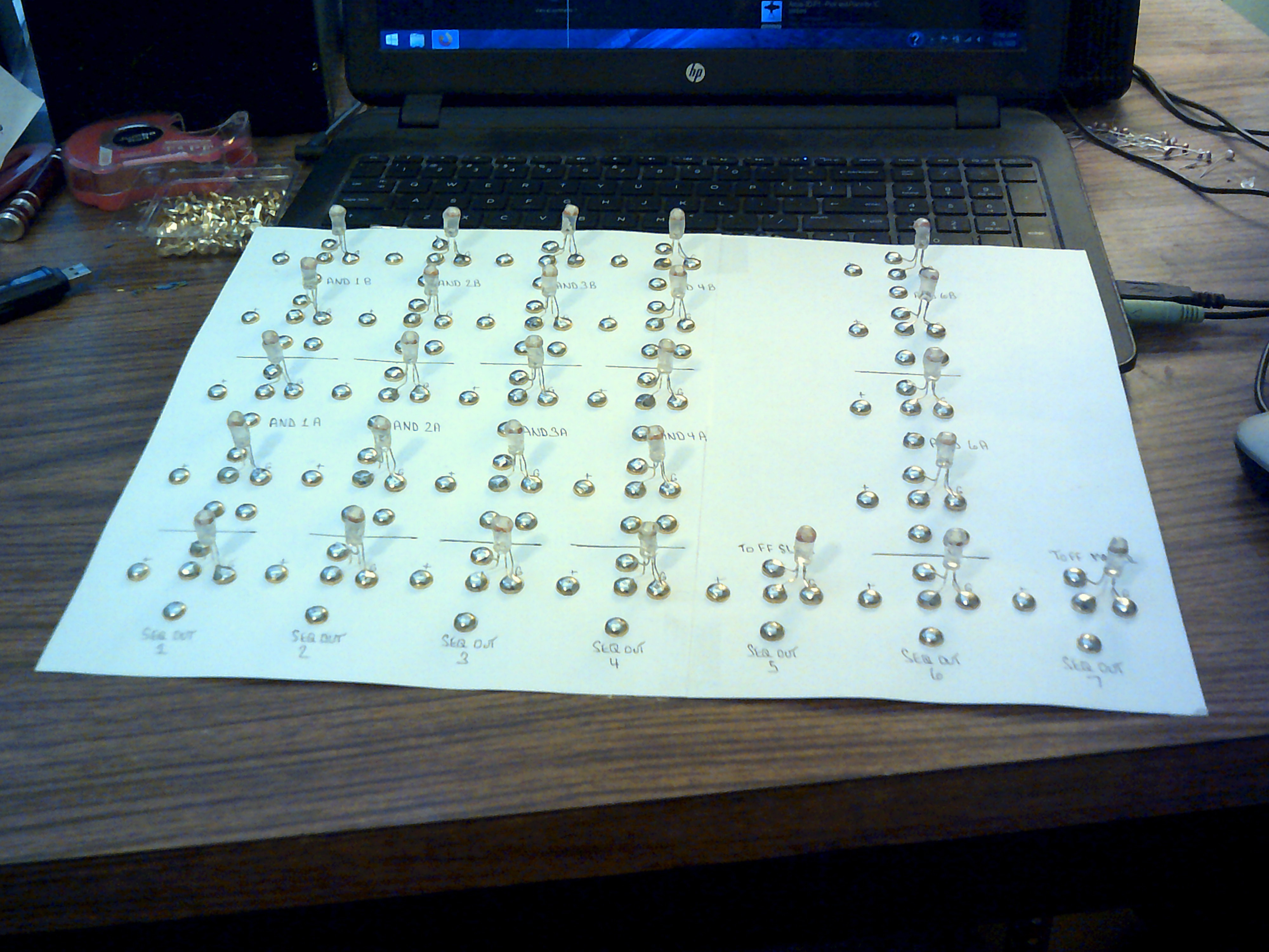
The front of the board showing the uncolored Light Logic opto-couplers in place.
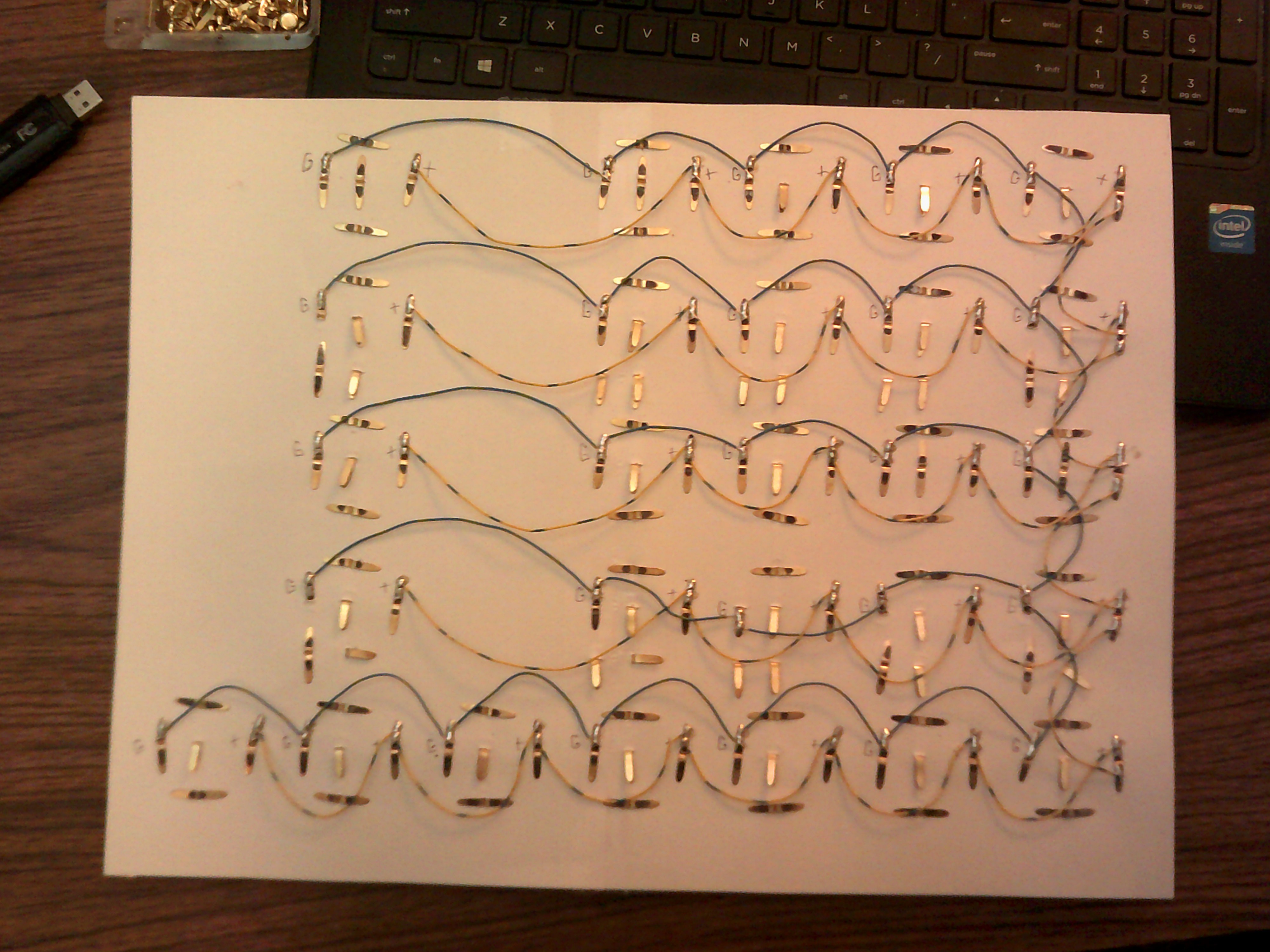
And the view of the rear side showing the power and ground wiring. This side will be hidden, thankfully.
-
Master Slave Duel D Duel Toggle Flip Flop ????
08/20/2020 at 21:44 • 0 commentsAugust 20, 2020 - What to do if you want to make a Master Slave Flip Flop but Light Logic does not like working with edge triggering. I improvised a couple of D latches into a Master Slave arrangement and toggled both latches separately with level triggering using the LLTP Sequencer. I might have a use for this circuit in my instruction logic.
-
LDA - The First Instruction Baby Step
08/16/2020 at 13:58 • 0 commentsWhile working on the Mux circuit, I decided to mess with the Sequencer and see if its output would actually control a simple task. After passing the selected output line through a level driver, the LDA instruction was born. Without decoding, the LDA instruction enables the Accumulator register on each loop at this time but proves to me that I am on the right track.
-
Sequencer / Ring Counter
08/14/2020 at 13:52 • 0 commentsI have decided to clean up and use the Ring Counter I designed last year and use it as the Sequencer for the LLTP.
This is the circuit for the initial 3 step Ring Counter. Just add extra steps in odd numbers and this circuit was expanded to the seven steps seen in the video. In the video there is a momentary switch wired off the board. This is used to start the cell reaction. In other circuits I have made, this switch was not needed as the sequencer self started. If the parts are closely matched then the switch is needed but if one cell has actual values that are a little off then the circuit tends to self start on that cell.
-
4 to 1 Mulitplexer
08/12/2020 at 01:11 • 0 commentsAugust 11,2020 - Time to start the construction of the Multiplexer. Simple basic logic circuit and typical construction using card stock and paper fasteners. The circuit is for one bit.
LLTP - Light Logic Transistorless Processor
My attempt to create a CPU/MCU without transistors or relays