It's time for an update here. :)
So far I've only posted pictures of the first prototype. To give you a little update about the current status here are a few pictures of the most recent build. There are also a few problems/"construction sites". For most of them I have already considered a few possible solutions. :)
The current state:
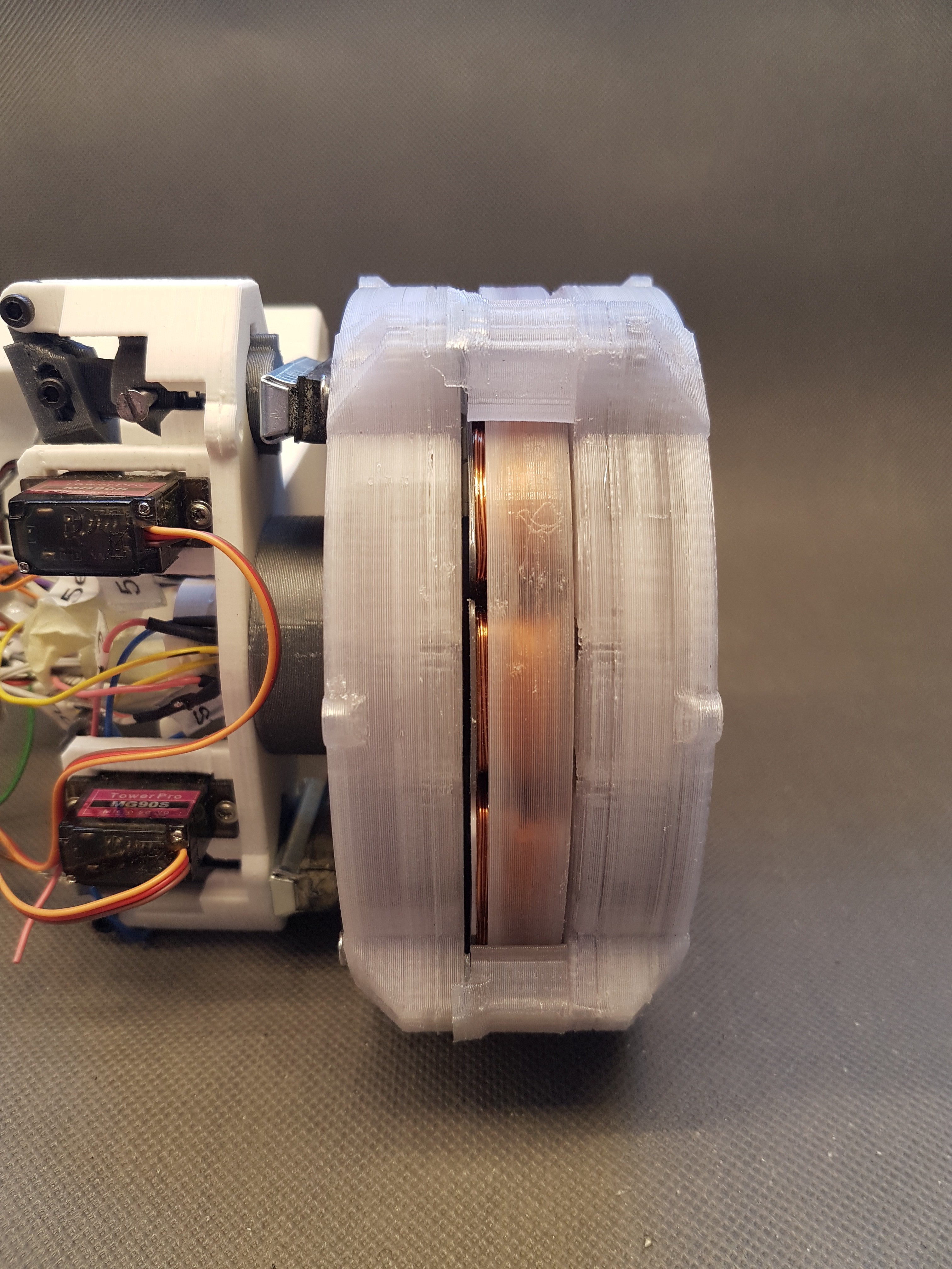
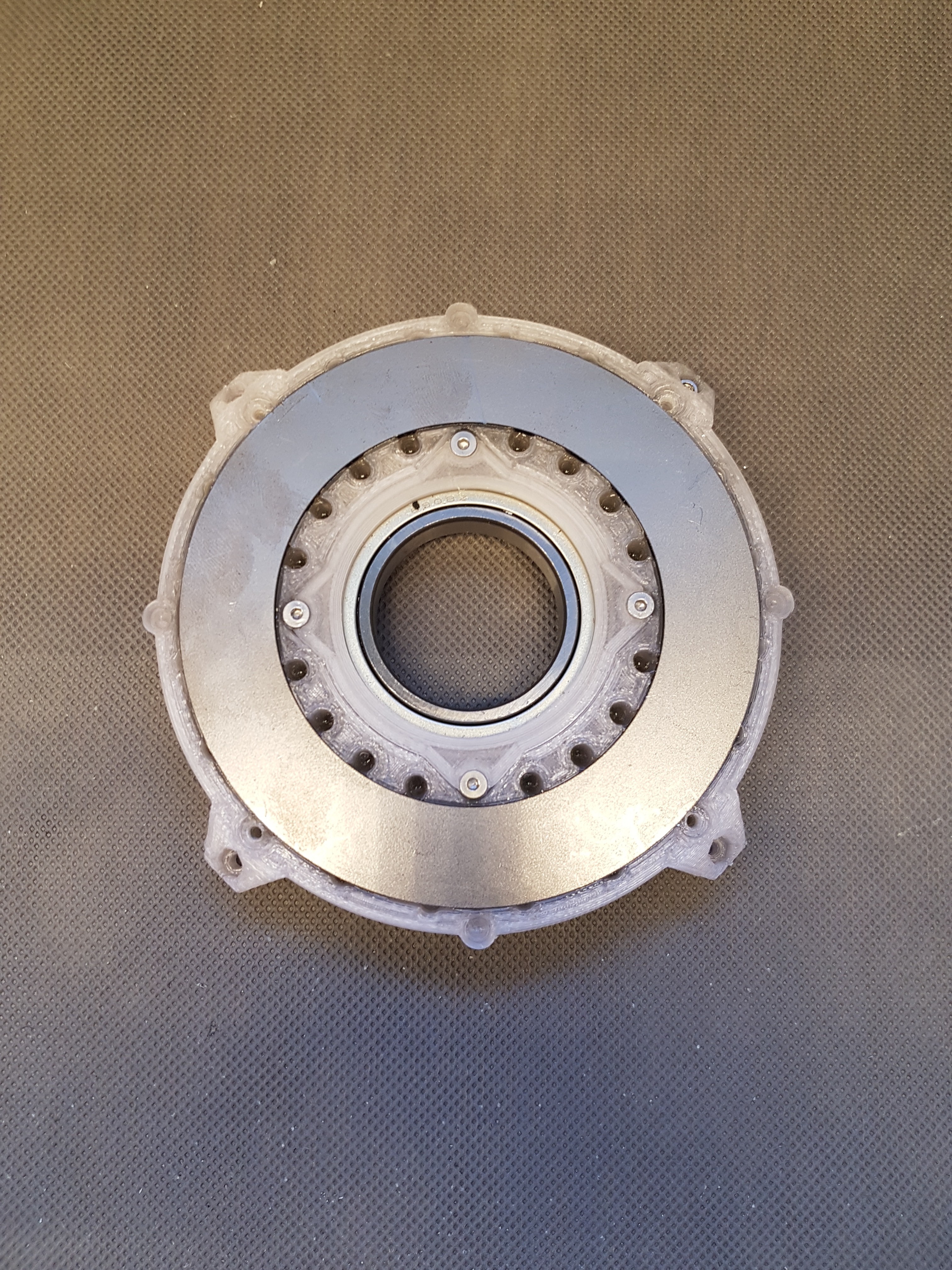
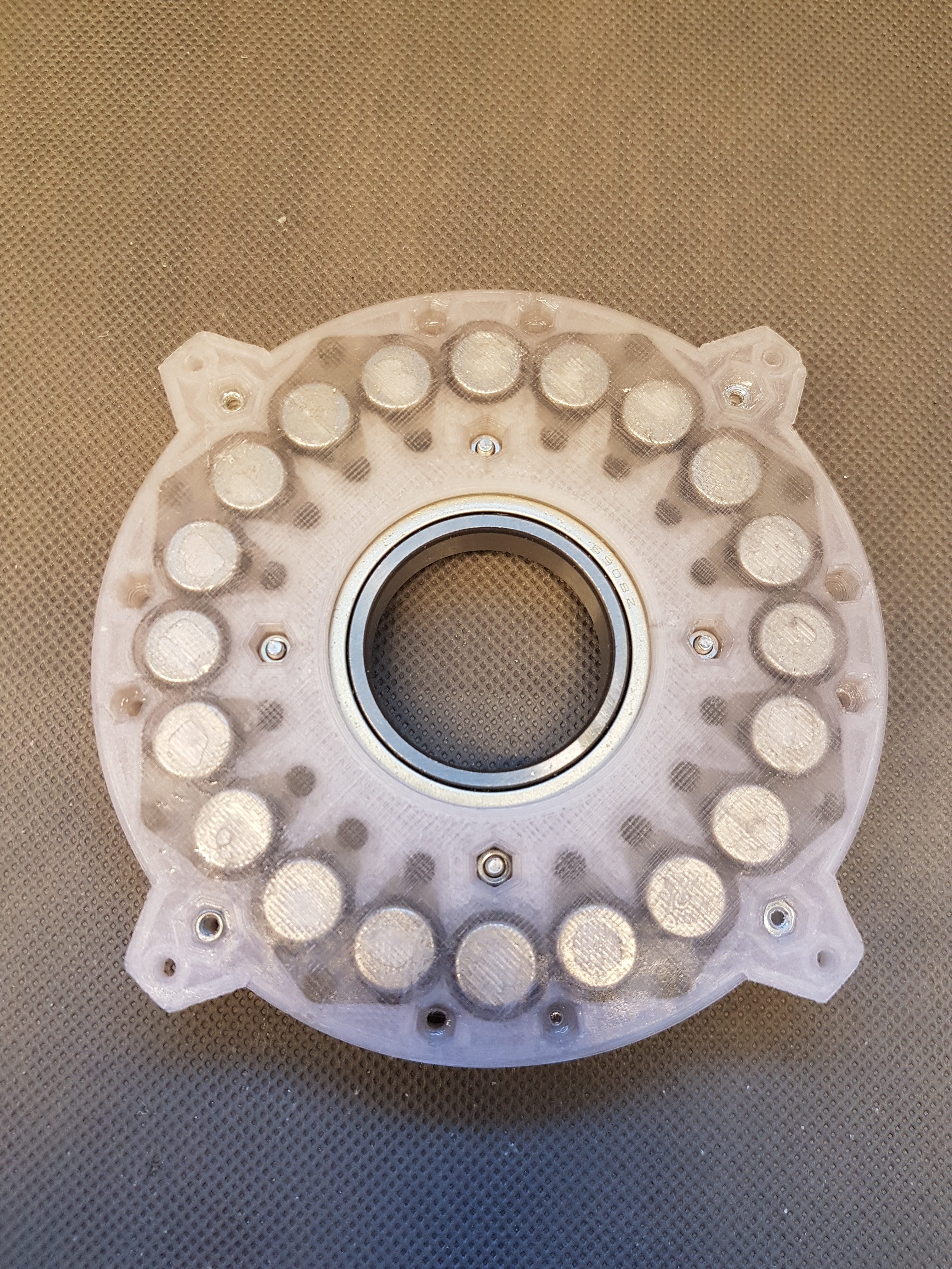
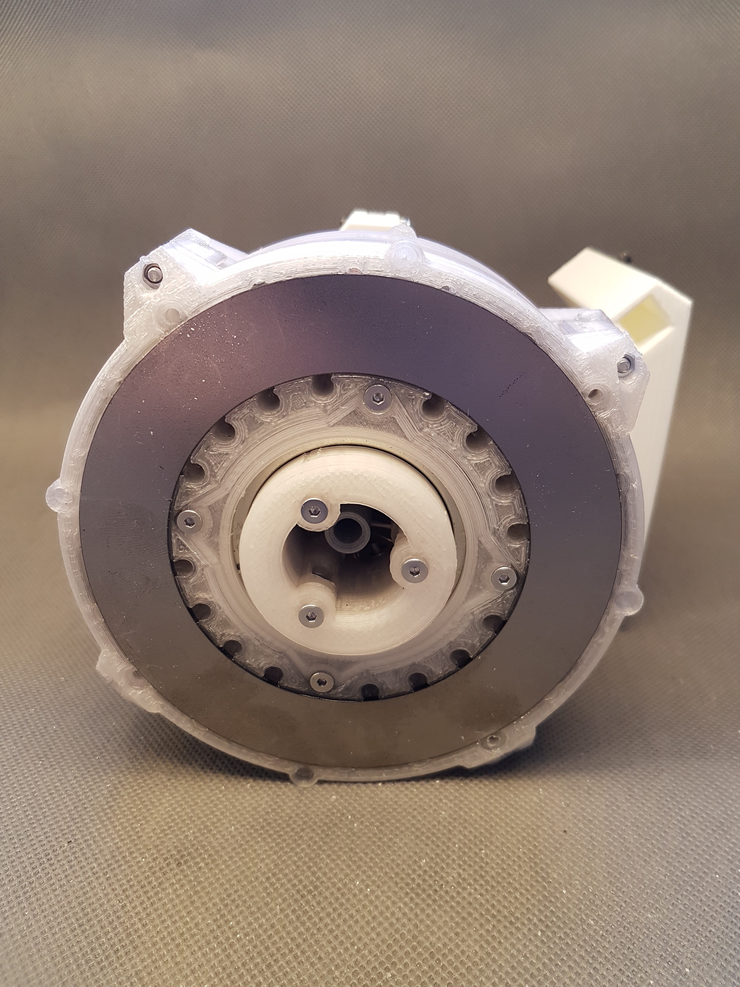
Here you can see the completely assembled generator in side and top view. I also removed a rotor disc (the disc that contains the magnets). Because this is where most of the changes are actually hidden.
A 2mm thick steel ring was installed on the outside of each of the two rotor disks. This has two and a half functions.
The first function is that it short-circuits the magnetic field lines of the neodymium magnets. This has the advantage that the magnetic field of the magnets outside the generator can no longer have a strong effect on other lines. In principle, it is a kind of magnetic field shield.
The second function is that this ring can be used as a friction surface for the mechanical brake system. The brake shoes of the planned brake can brake the generator by pressing onto these discs. The steel surface should be much more durable than the 3D printed surfaces. :)
Half the function is that it makes installing the magnets in the rotor a little easier. The magnets can be screwed into the rotor using the ring and four screws. In this way, the remaining cavities can be filled with epoxy in peace.
Here the pictures. More about the issues a bit below. :)
Now for the first problem:
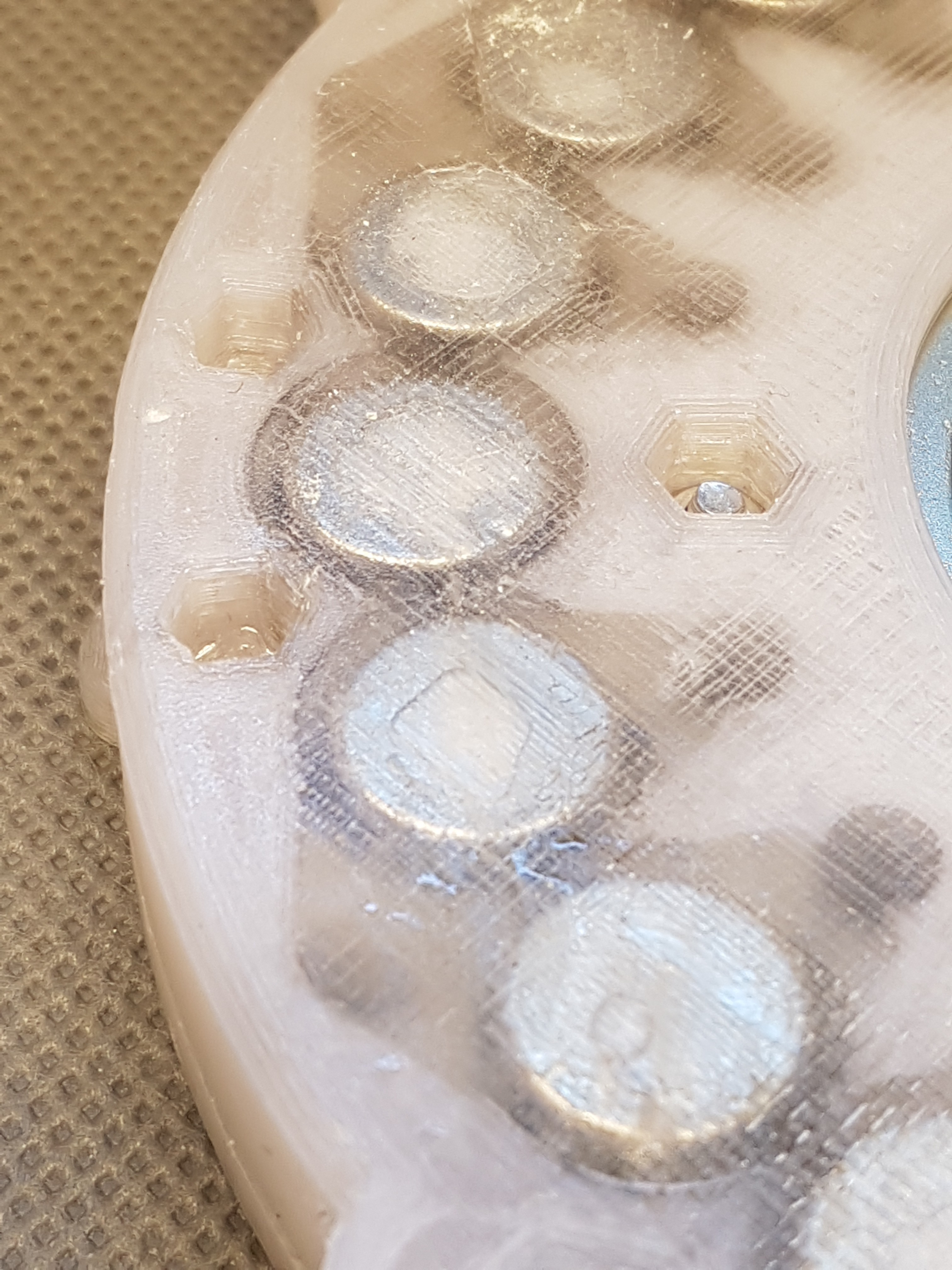
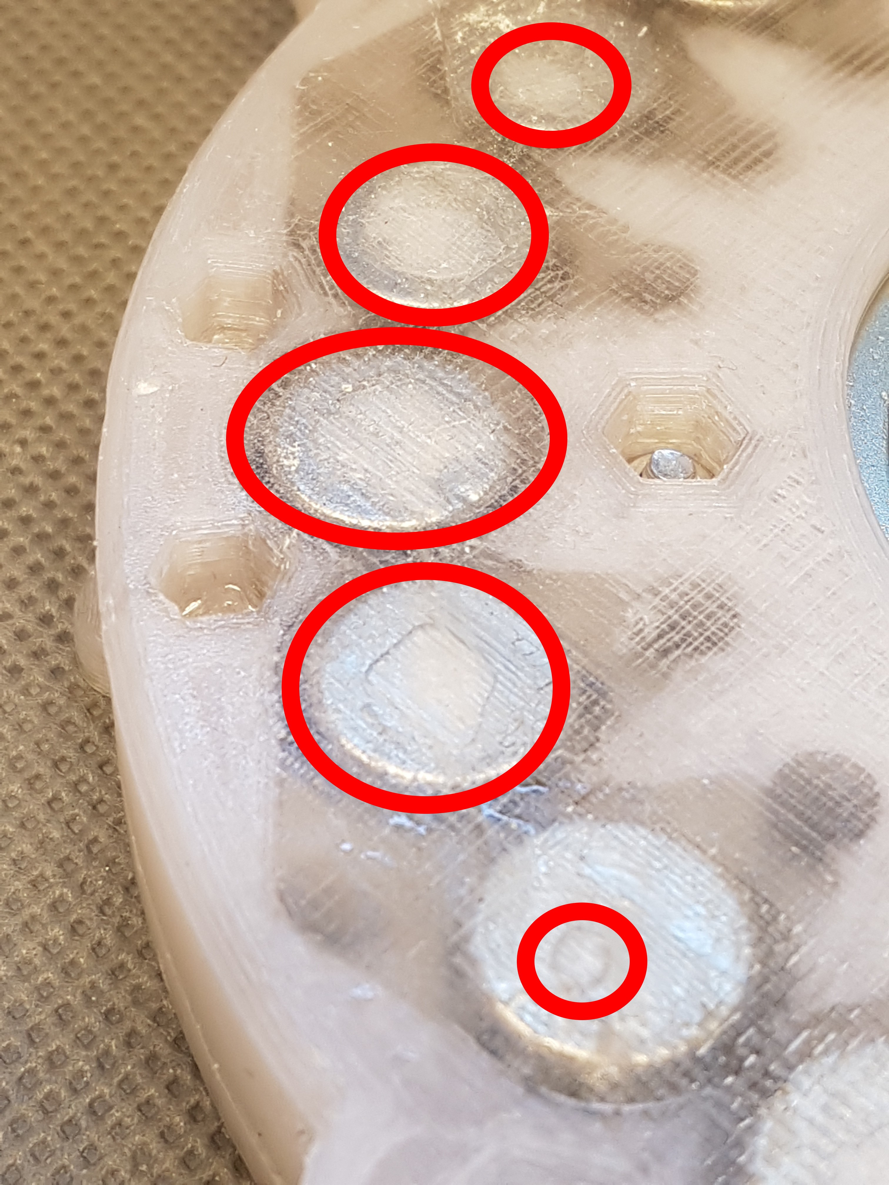
On these two pictures you can see that there are air pockets between the 3d printed housing and the magnets in the rotor disc. (I marked it on one of the pictures). This is not so great, because on the one hand it could increase the distance to the stator disc (this should be as small as possible, because this corresponds to the air gap in a generator) and on the other hand the magnets should be completely encapsulated from all sides in order to make the construction as stable as possible and more important to get an even weight distribution. Otherwise it could happen that the rotor develops an unbalance despite its symmetrical structure.
In order to prevent this, I planned to expose the rotor disc to a slight vacuum for a certain time after filling in the epoxy and hopefully be able to pull all air bubbles out of the epoxy. I built a small vacuum chamber for this. (I will present it in another project log soon.)
I hope it works. :)
The next problem:
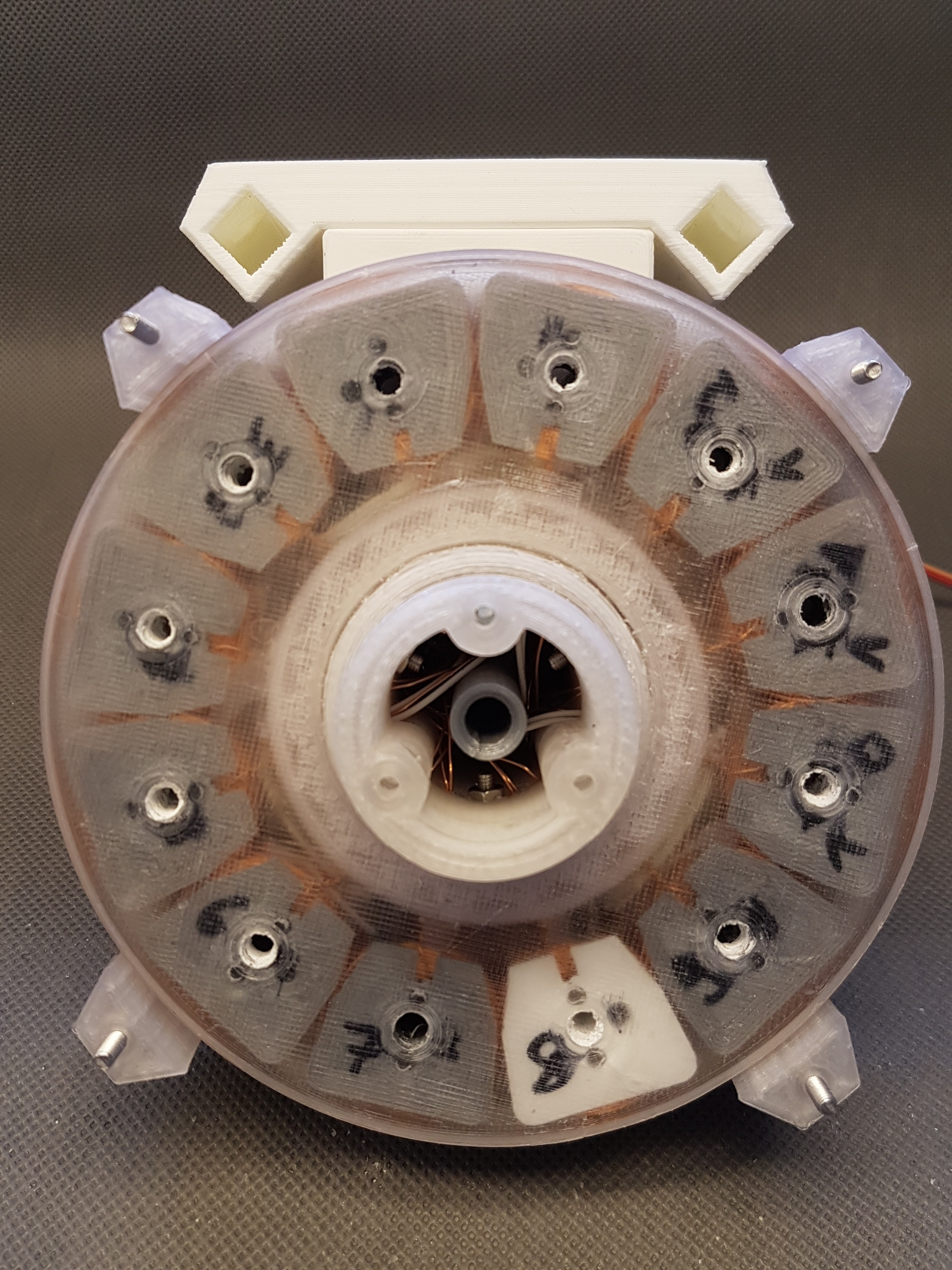
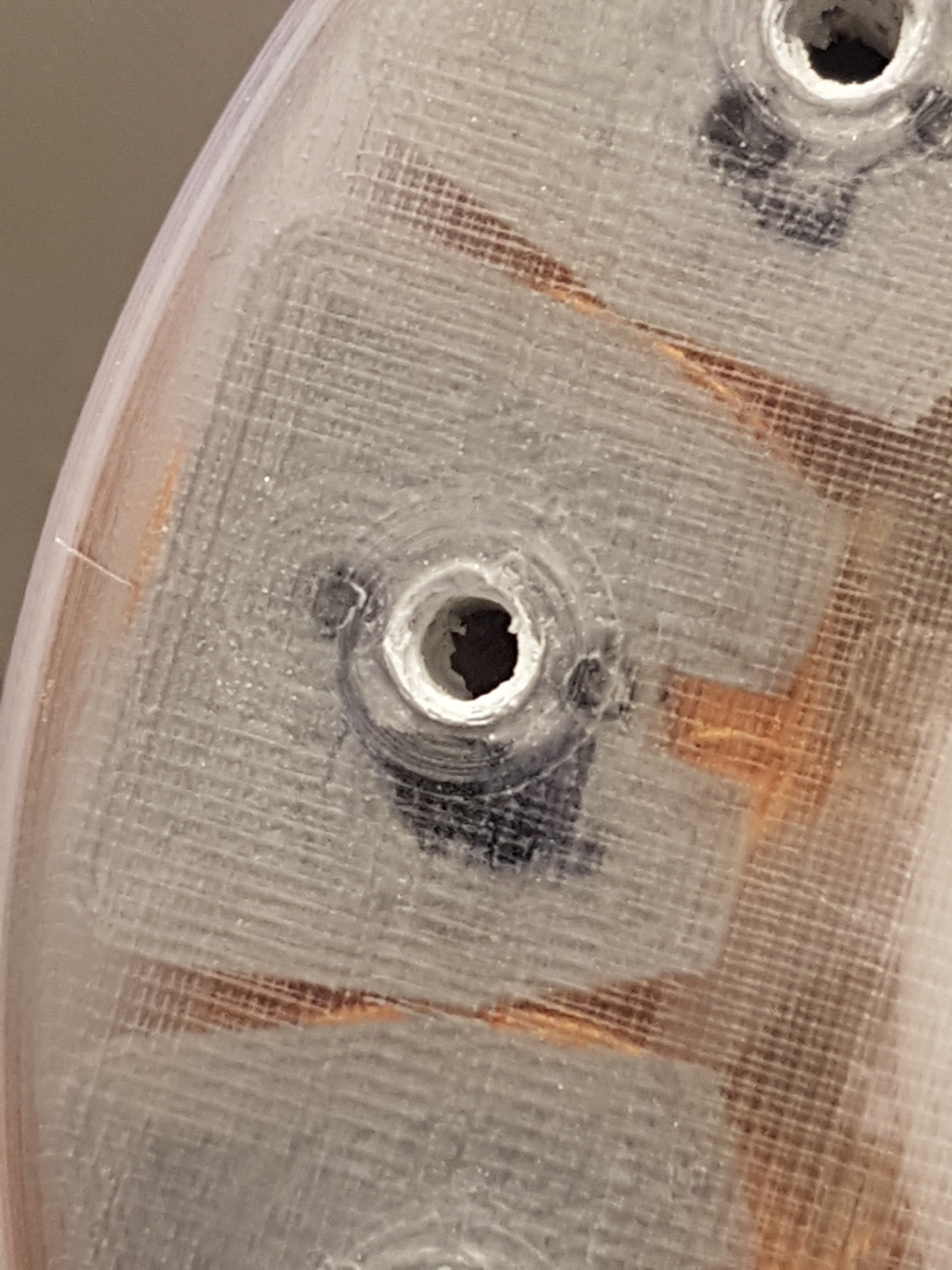
While filling the stator washer with epoxy, I temporarily screwed the coils onto the stator well with M5 screws. Unfortunately, this screw connection is not really tight, so that epoxy runs out of the screw-holes and out of the stator during filling.
To prevent this, I want to seal the screw holes with rubber washers. That should actually work. I'll see if it works when building the next version. :)
In the second picture you can still see that the hole with which the coils were fastened is interspersed with epoxy. At first it was quite difficult to remove the screws from the stator washer. : /
 Fabian
Discussions
Become a Hackaday.io Member
Create an account to leave a comment. Already have an account? Log In.