 Fabian
My last attempt to build an actuator for a mechanical brake went pretty wrong.
At that time I tried to press two bicycle brake blocks onto the rotor of the nerdiskerator with the help of two SG90 servos. As a result, the rotor should then slow down and ultimately come to a standstill.
Unfortunately the servos could not apply enough pressure. But see for yourself:
Next design
In order to be able to press the brake block onto the rotor with a little more pressure, I thought about a new design. This consists of two gear motors, of which each presses the brake cylinder onto the rotor of the generator via a small reduction-gear.
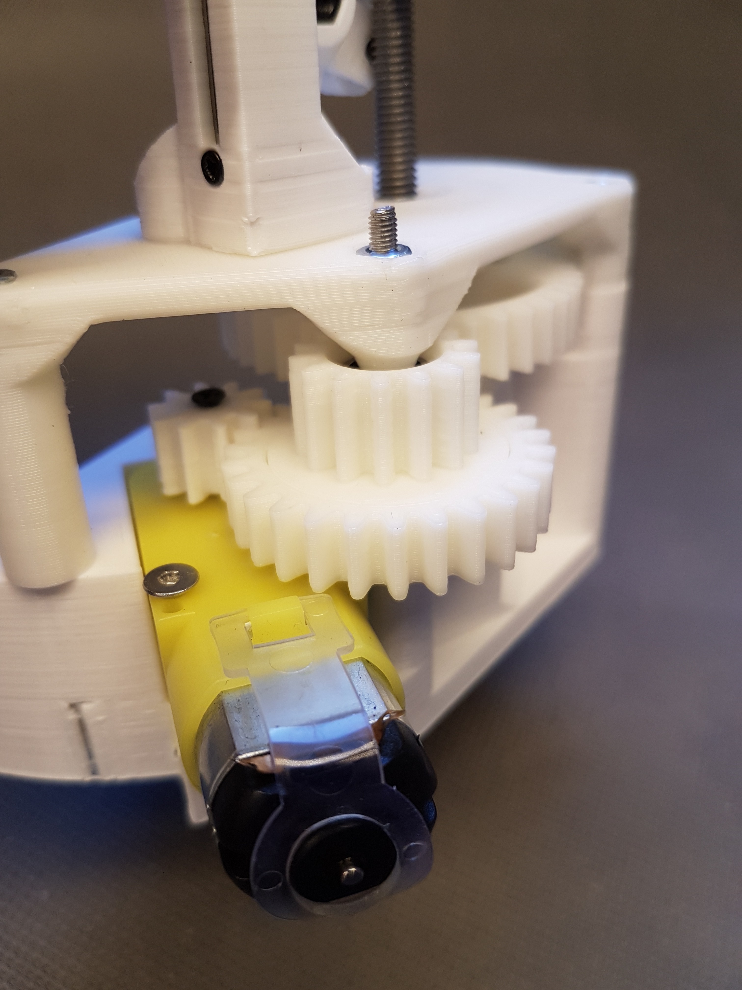
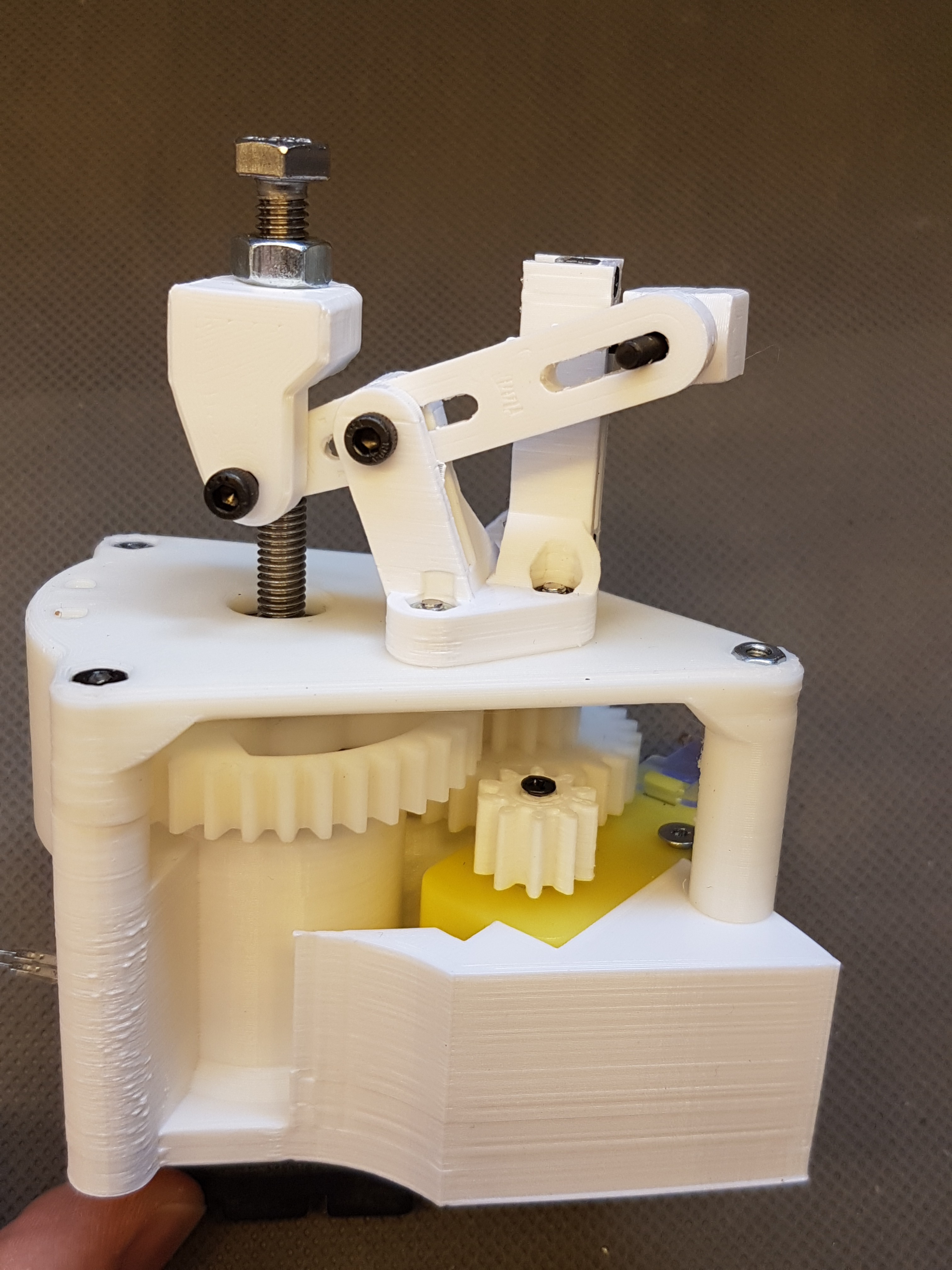
At the beginning I experimented with the same (too weak) dc motor that I had already used for the pitch actuator. Unfortunately this was too weak for the brake actuator, which is why I later switched to the same geared motors that I use for the latest draft of the pitch actuator.
Design using (to weak) dc motor
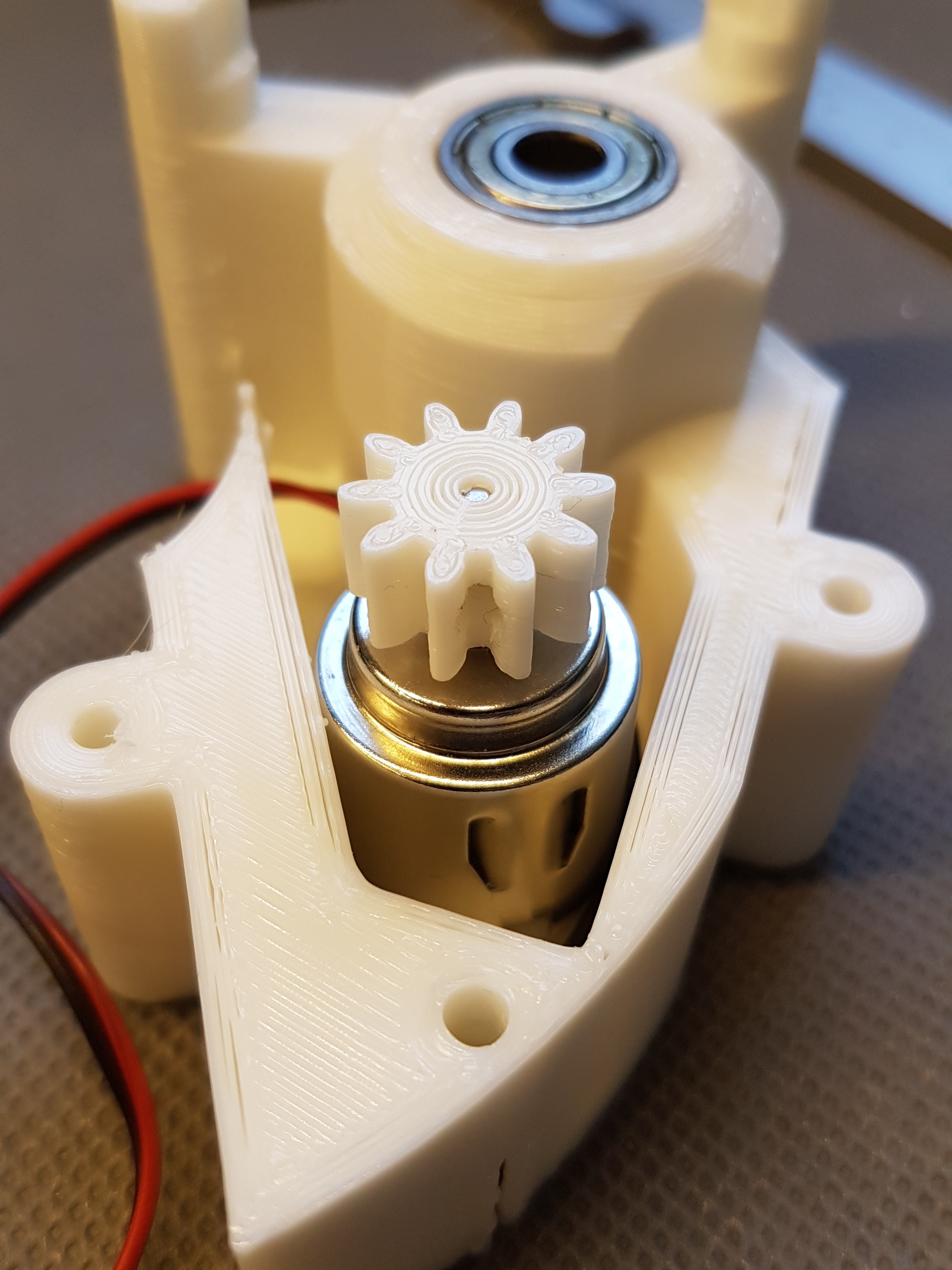
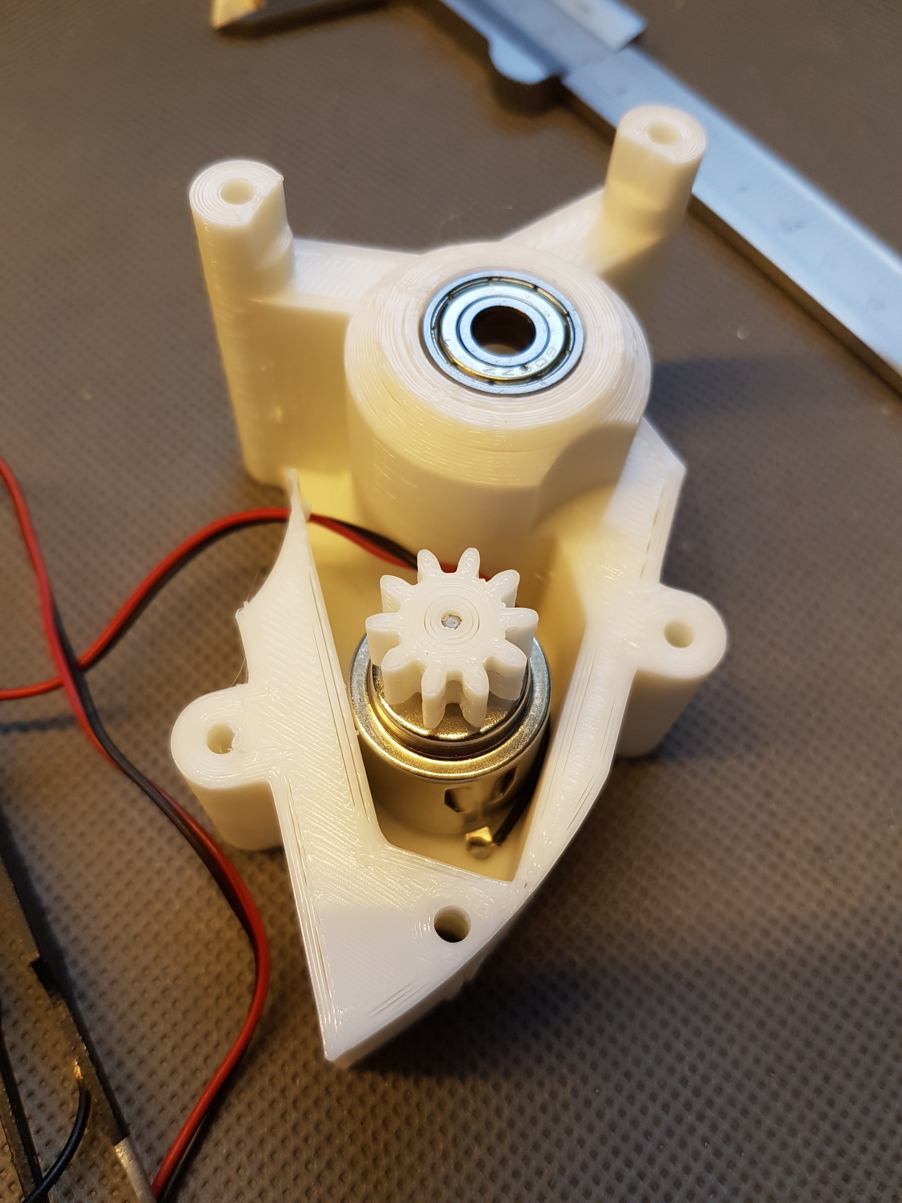
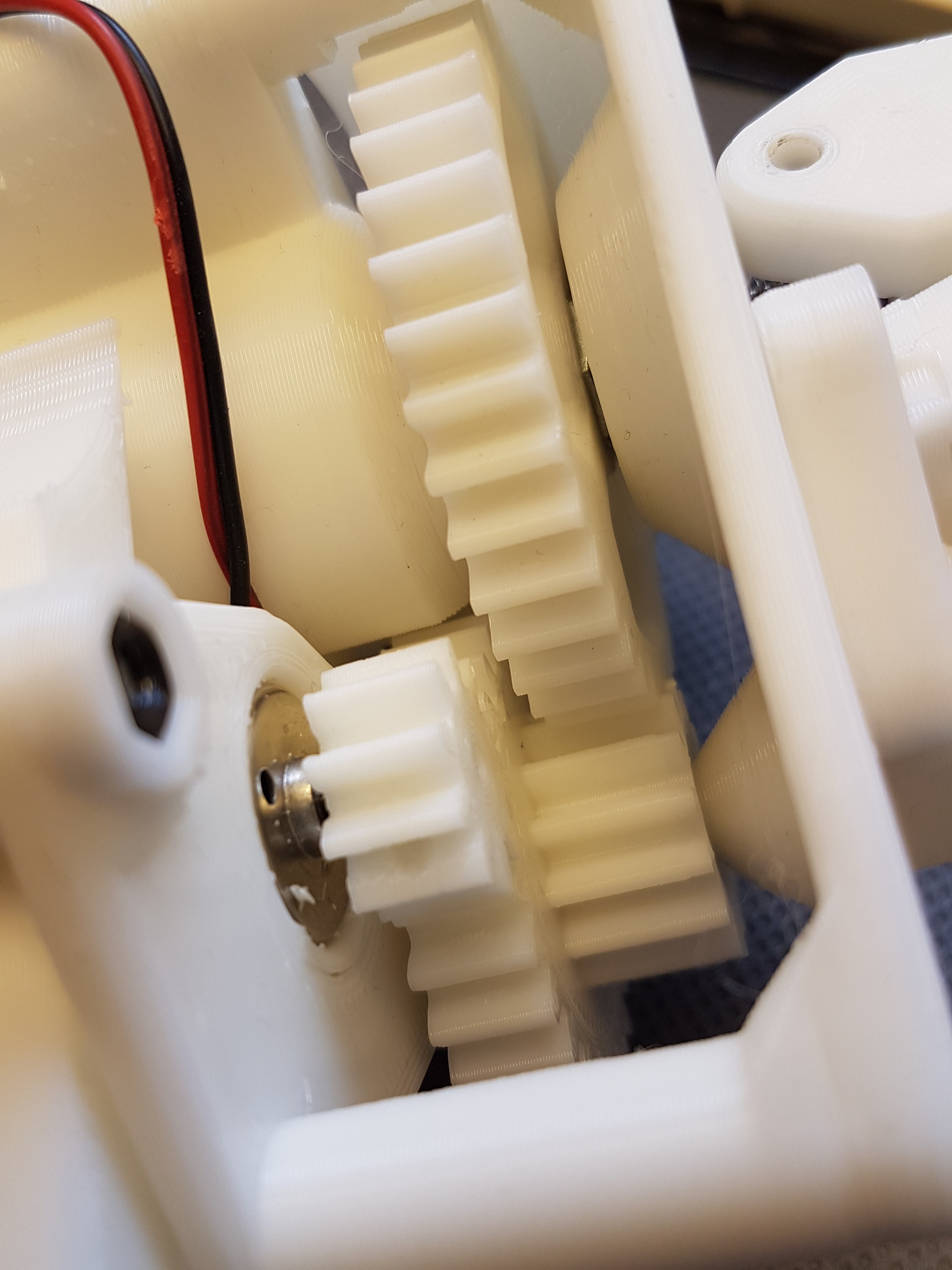
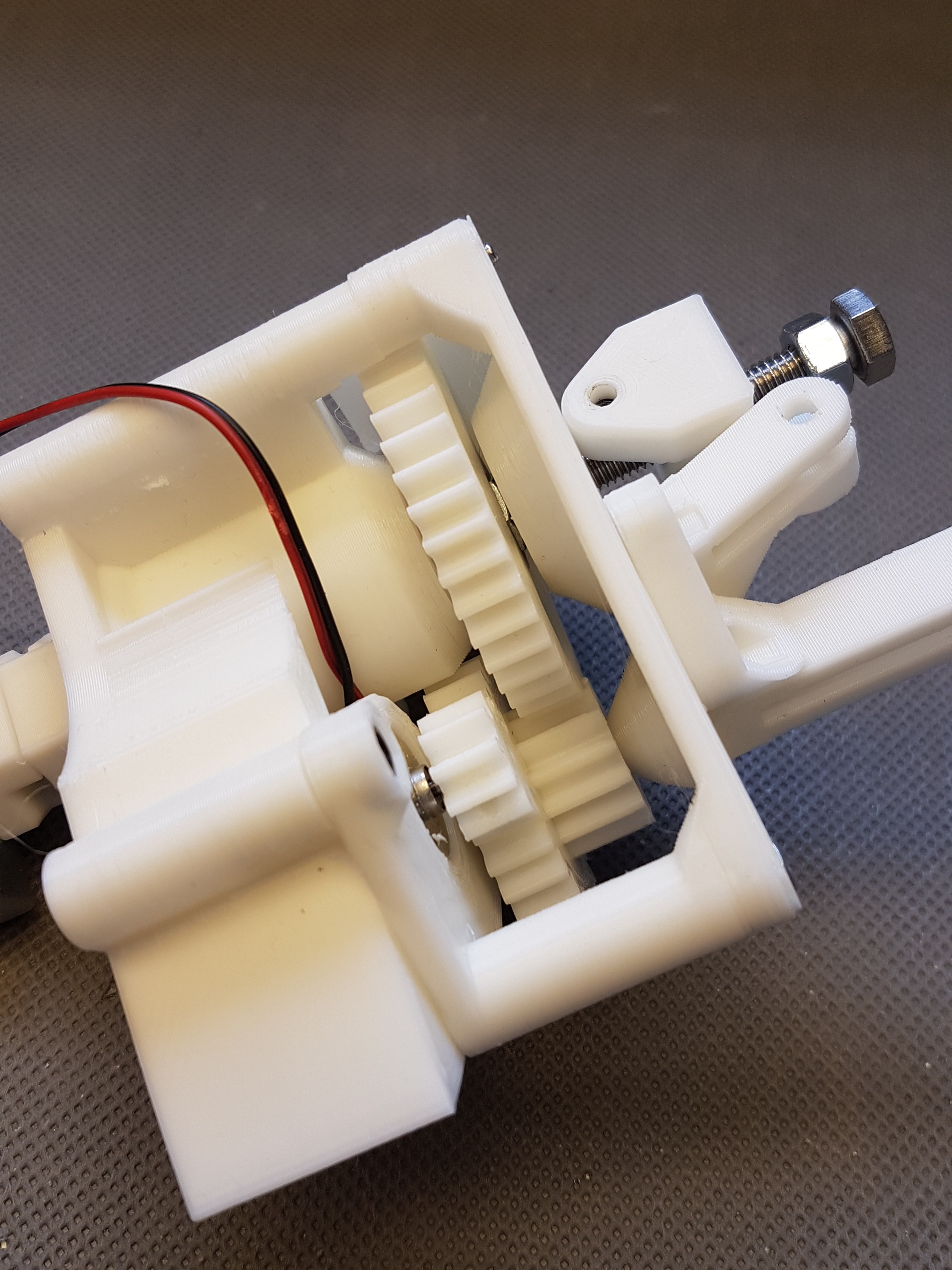
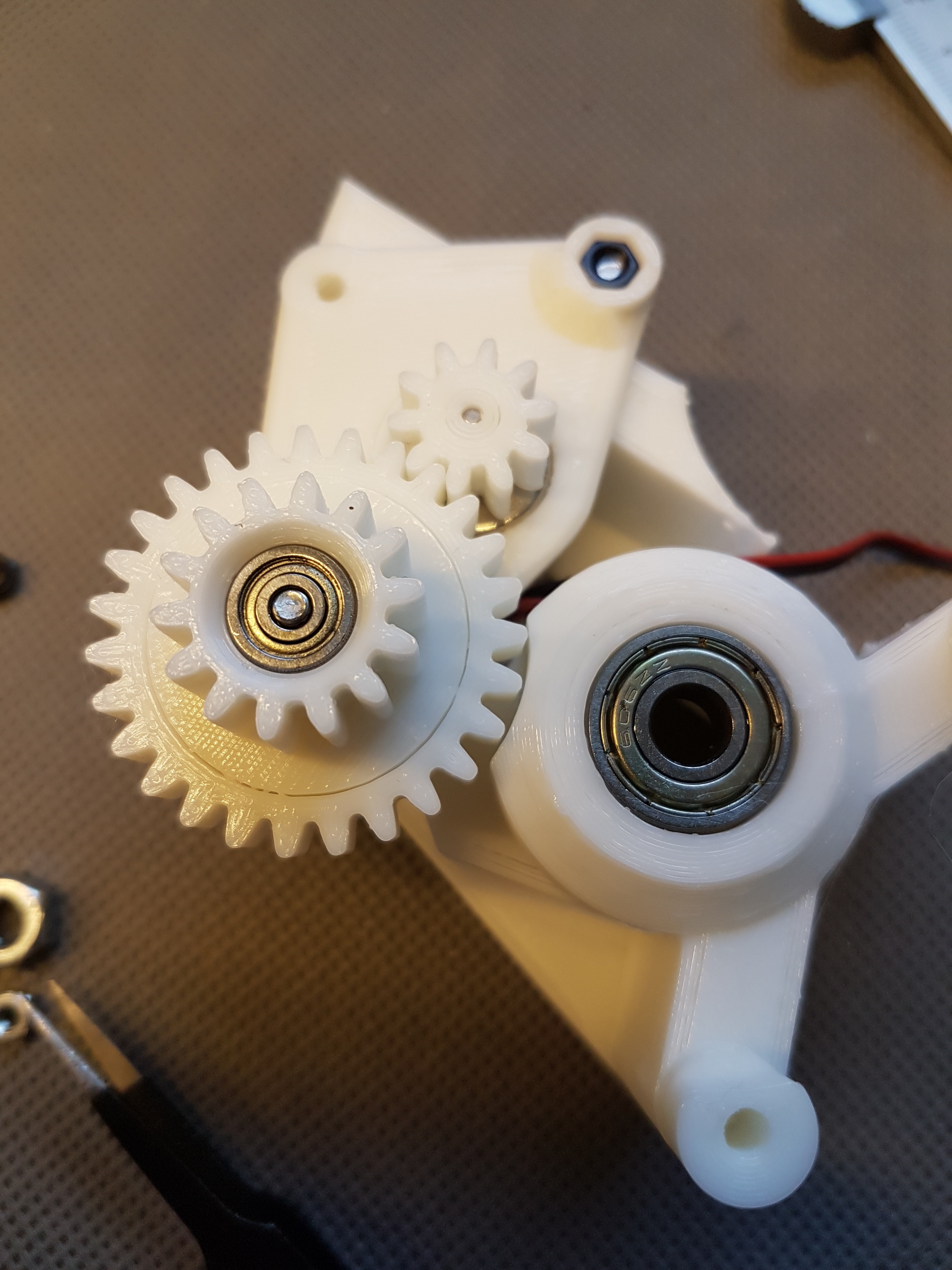
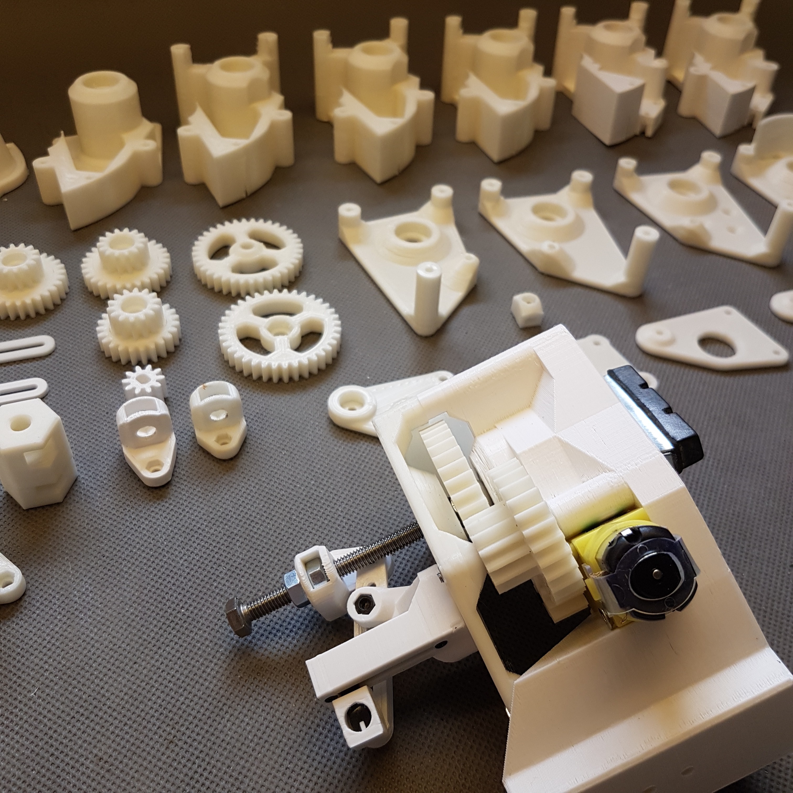
Design using a geared motor
A video of the running prototype is visible here: https://www.instagram.com/p/CDGdRvbKCRp/
Some pictures here:
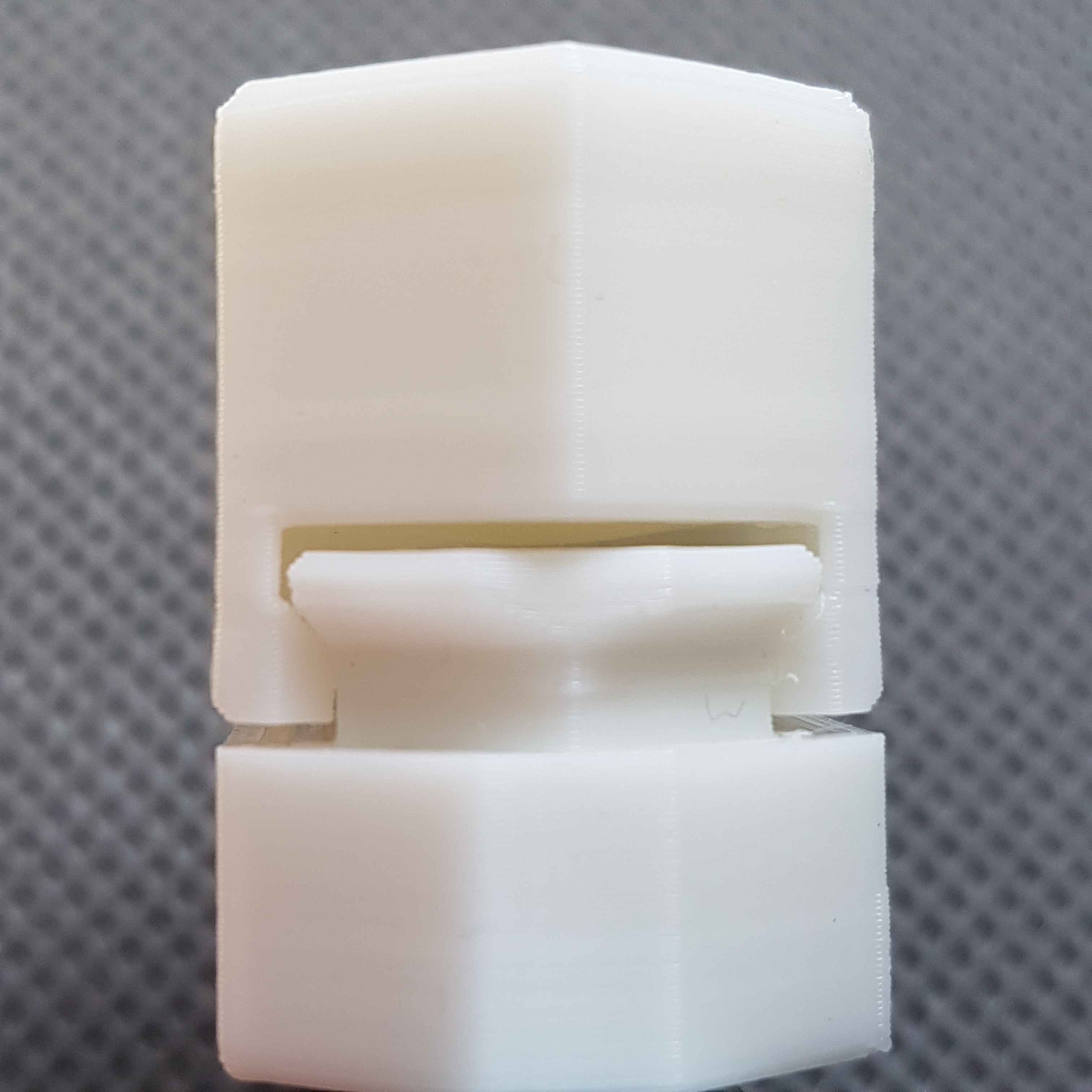
So that the position of the brake cylinder can always be absolutely determined, a sliding resistor is coupled to the brake cylinder via a lever reduction on the back. So 5 to 7mm movement of the brake cylinder are "scaled up" to the 20mm of the sliding resistance. So you can take advantage of the whole "resolution" of the slide-resistor.
More information is also available in this post: https://www.instagram.com/p/CDTp1OXKpsS/
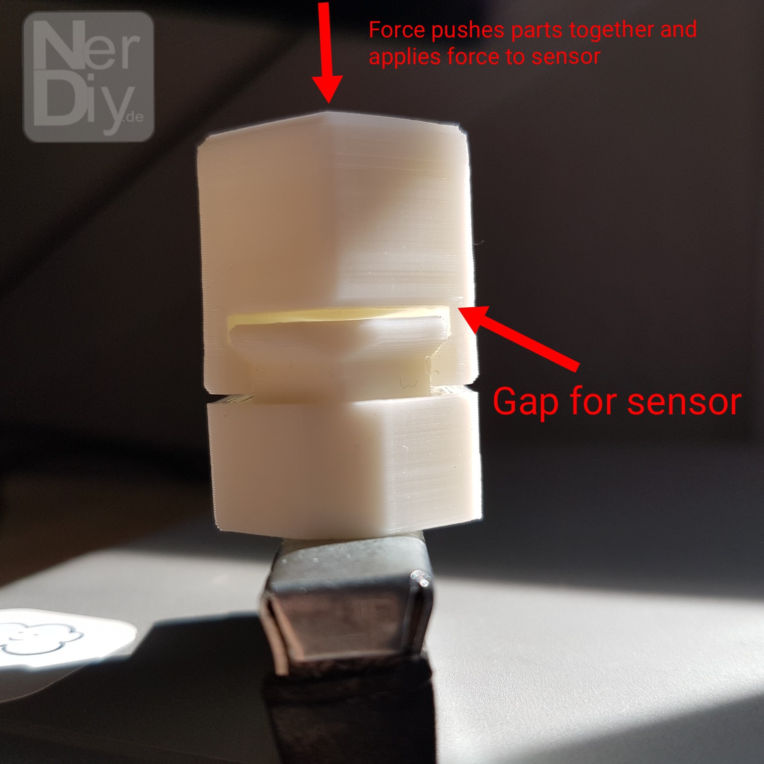
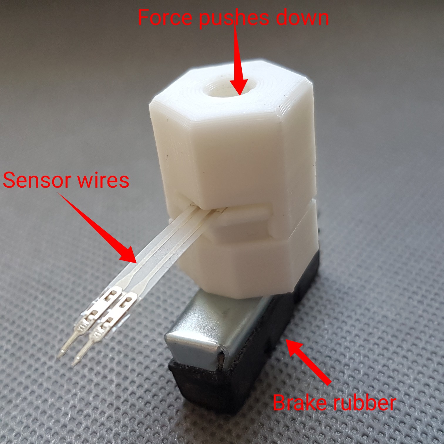
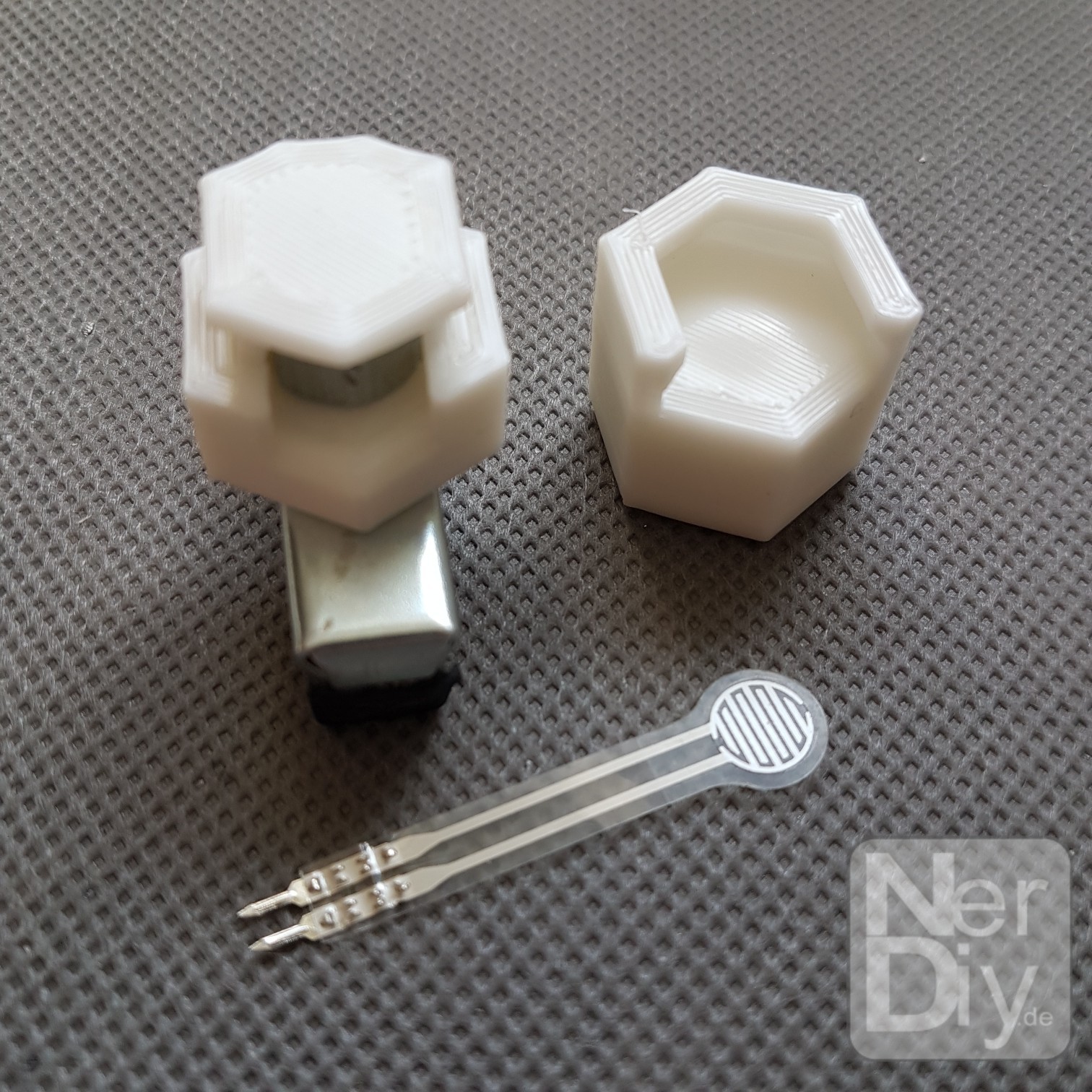
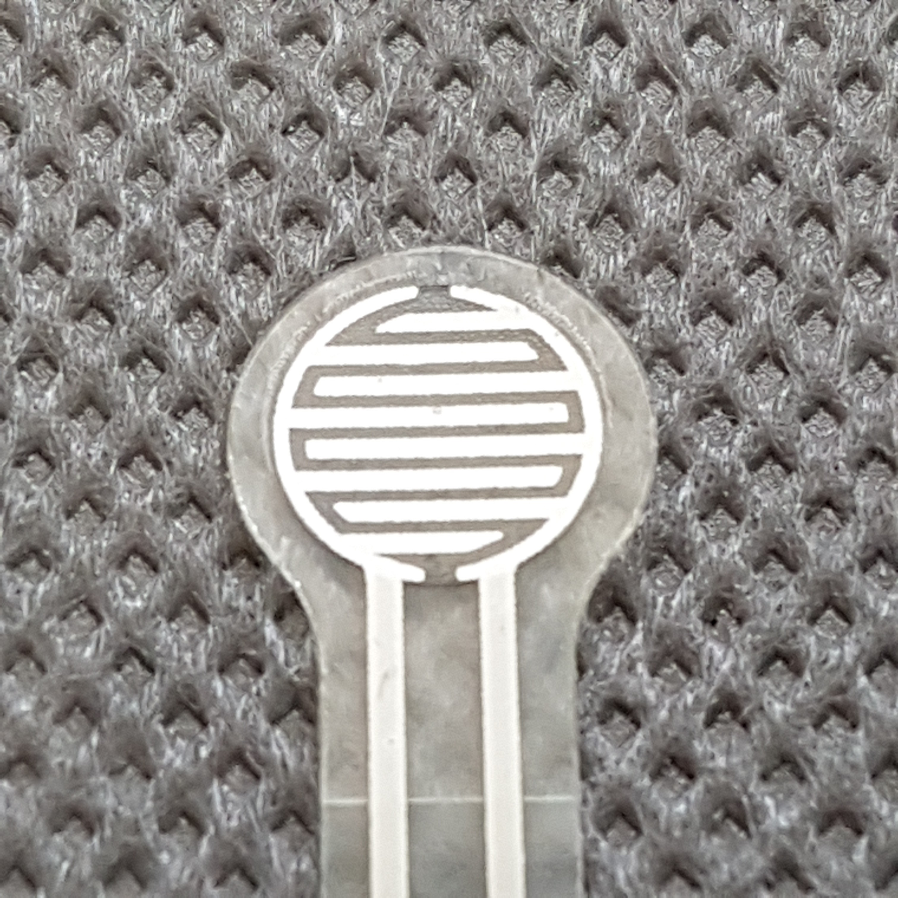
I also installed a force sensor in the brake cylinder itself. This should measure the force with which the brake cylinder is pressed onto the rotor. You can read a few more details about this here: https://www.instagram.com/p/CDl4wGYKugw/
Some more pictures about that:
Last but not least, I plan to use an i2c motor driver to control the dc motors. Thanks to a shunt resistor, it can also measure the motor load. This allows the controller to recognize any unusual load and switch it off.
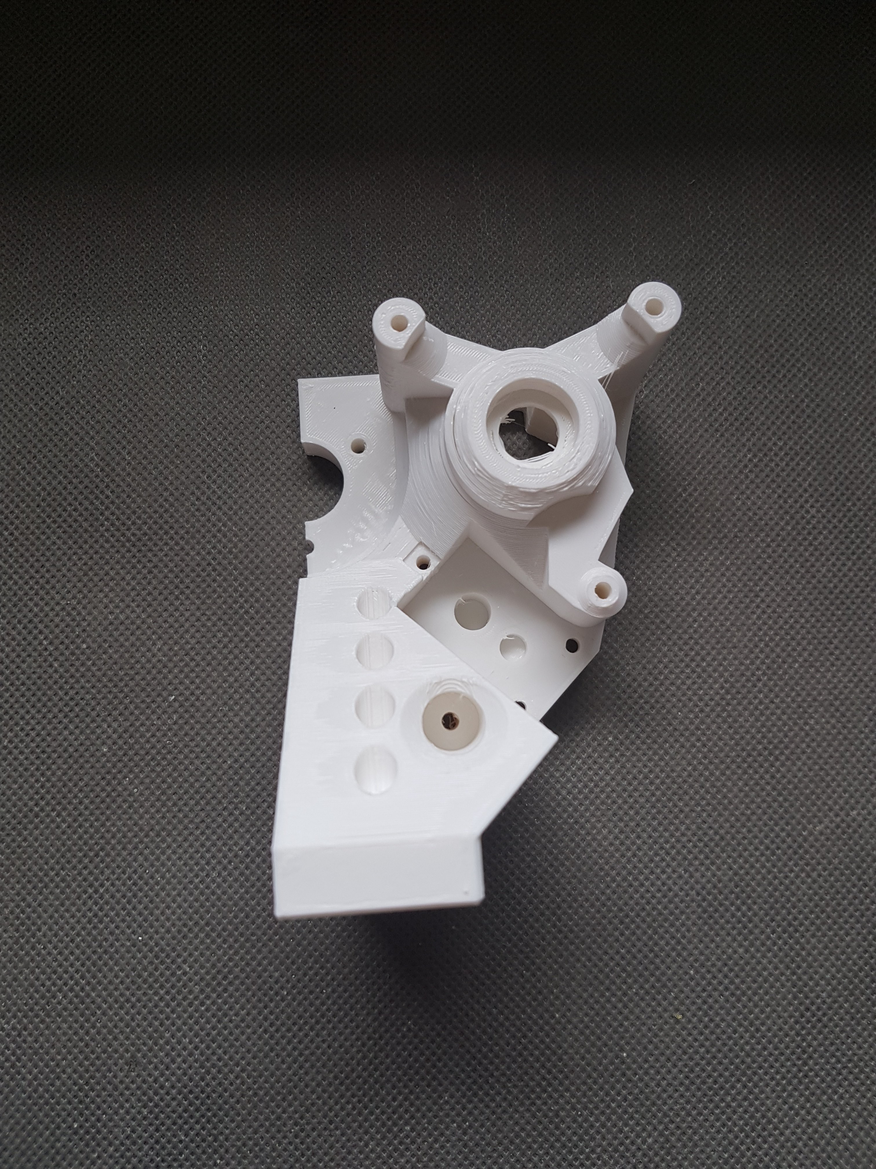
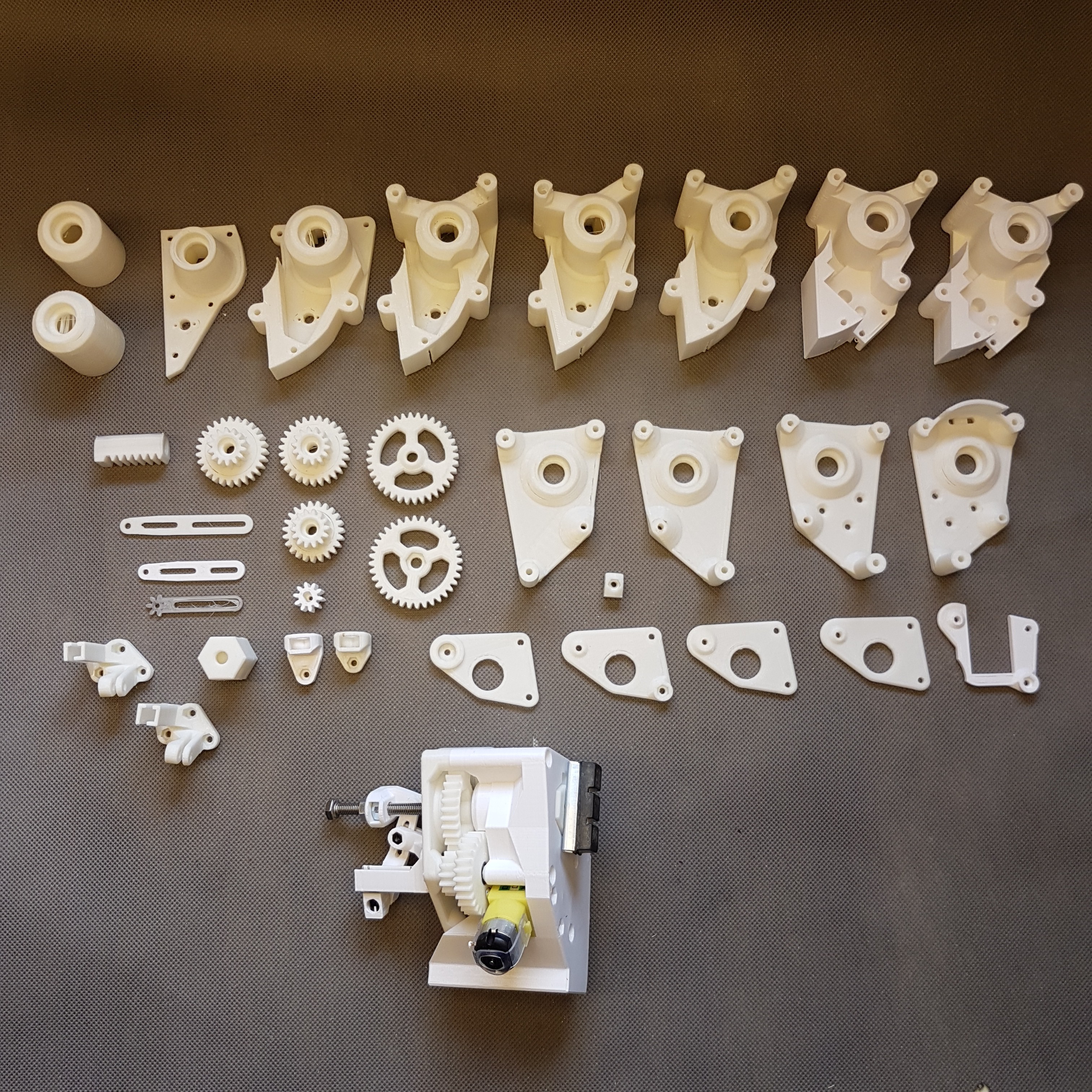
After all this itteration i had created a huge collection of different failed parts that were iterated part by part.
A small overview of this parts:
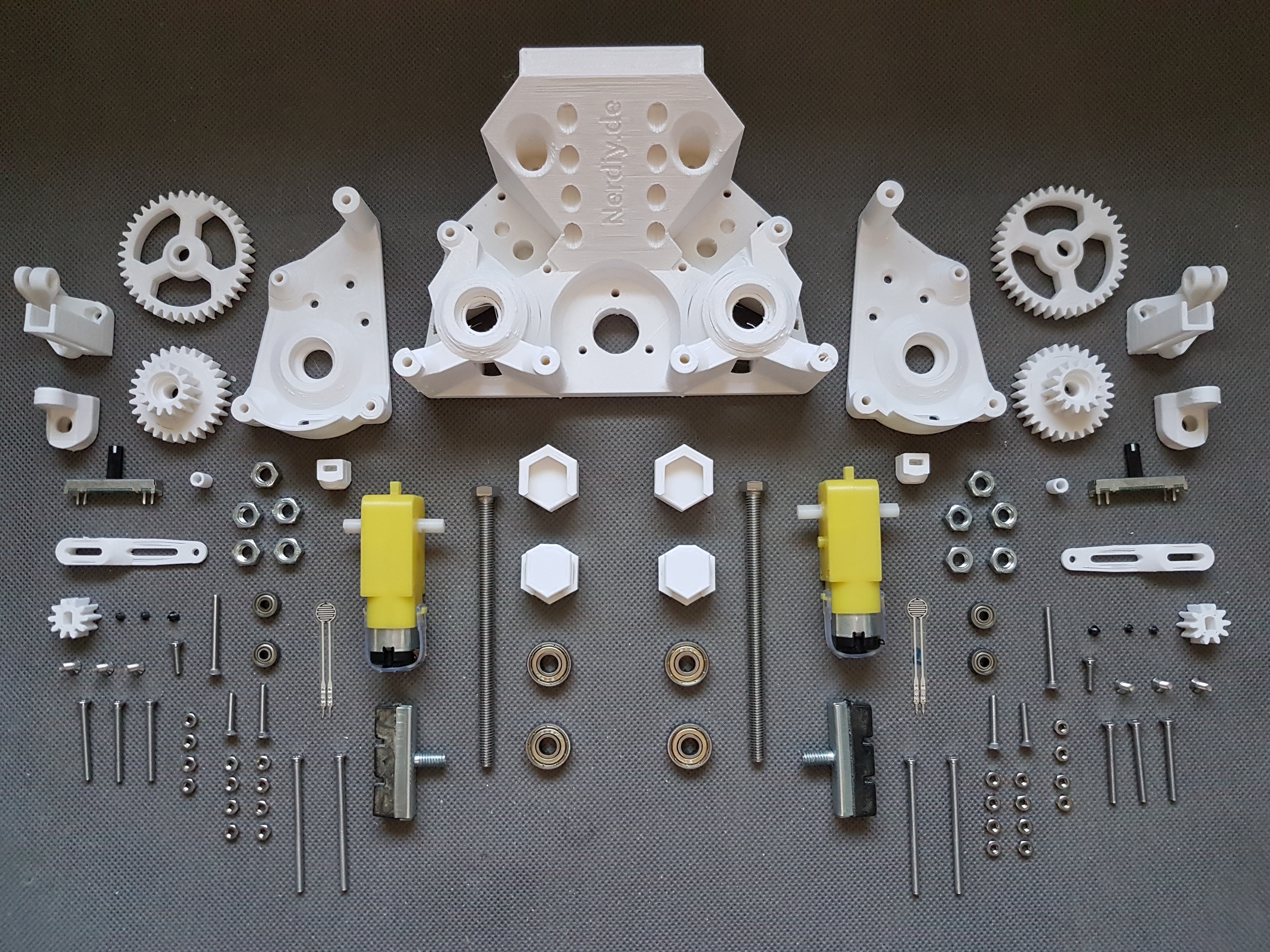
Finaly I reached the actual state:
Two brake actuators integrated in the mount of the nerdiskerator:
A quick overview about the used parts:
Took me a while to finish this part but now I'm pretty happy with it. :)
Discussions
Become a Hackaday.io Member
Create an account to leave a comment. Already have an account? Log In.