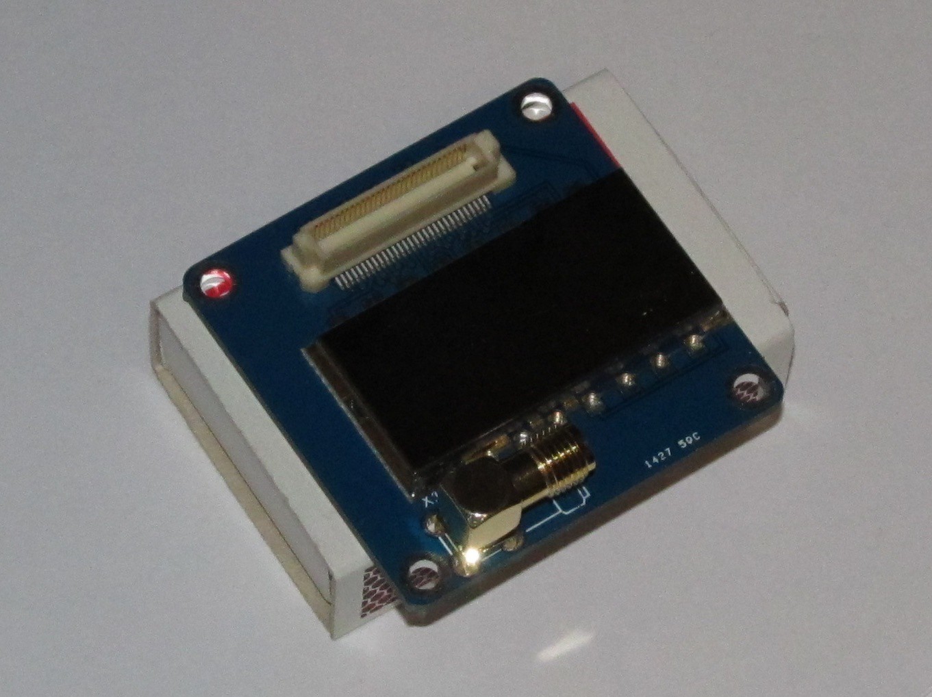
Version 0.1 PCB's have arrived from Seeedstudio today, along with the RF modules themselves. There a few more than the five I ordered, so thanks Seeed!
Considering these are the first PCB's I've had manufactured, I didn't expect them to be perfect, from a design perspective. First thing I noticed was that the holes for the locating pins on the 60 pin connector are missing. My footprint in Eagle had the holes in the holes layer. Not sure if it was how I generated the Gerbers, but maybe I should just put them in the drills layer to be safe? If anyone has a better way, please let me know in the comments.
I drilled some slightly oversize holes to allow the connector to sit correctly. A quick dummy assembly followed. To give an indication of size - the board is sitting on a matchbox!

The silkscreen is missing some of the additional text that I included in the files in the Dropbox, but it also doesn't name the components correctly. Something to fix for the next rev.
Before the boards arrived, I had reviewed the design and found a few issues.
1. I had not followed the correct process for passing through signals from the bottom connector to the top connector.
2. Vcc trace is too narrow for full power
3. Need a capacitor on the Vcc line.
4. Vias for power pins on backplane need to be larger, or more than 1 via for the power bus passthrough pins
Just in time for Rev 0.2, a new local ( in Australia anyway) PCB manufacturing company (Breadboard Killer) has advertised on Twitter a great deal on PCB's - $2.50 per sq inch! So that's 3 of these boards for $7.50!!!
I'd better get moving!
 OzQube
Discussions
Become a Hackaday.io Member
Create an account to leave a comment. Already have an account? Log In.