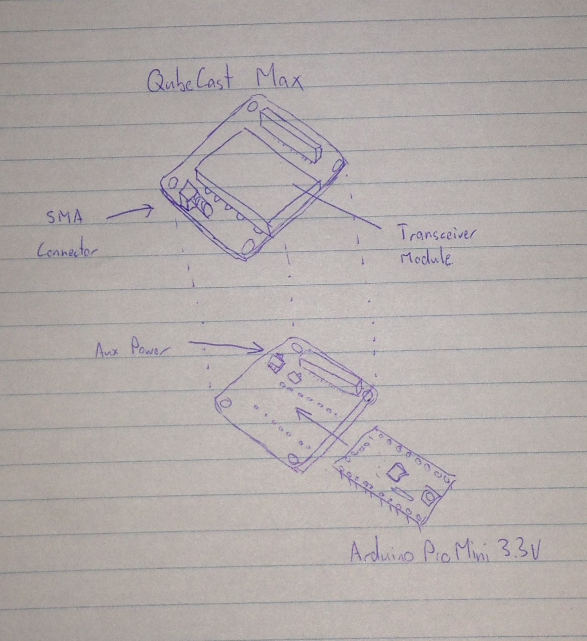
So I need a system design document to meet the entry requirements. In case the design isn't clear from the description, the project logs and the video, here's a basic diagram:
All the software/coding is done on the arduino.
And an actual update - the Arduino Adapter board still hasn't arrived :-(
I've been considering alternatives for powering the test board. The following are some options:
1. A TI TPS63001 Buck/Boost regulator on the Rev2 Arduino Adapter, which will allow the setup to run from a LiPo battery
2. One of the Linear Tech charging IC's that has a built-in regulator....but that may be more expensive. It'll let me run from USB and charge the battery in a single IC though.
3. Find something in the SeeedStudio Open parts library that I just received.
Open to suggestions, so feel free to comment :-)
 OzQube
Discussions
Become a Hackaday.io Member
Create an account to leave a comment. Already have an account? Log In.