 rex
rexBackground
I recently noticed that my mail had been tampered with.
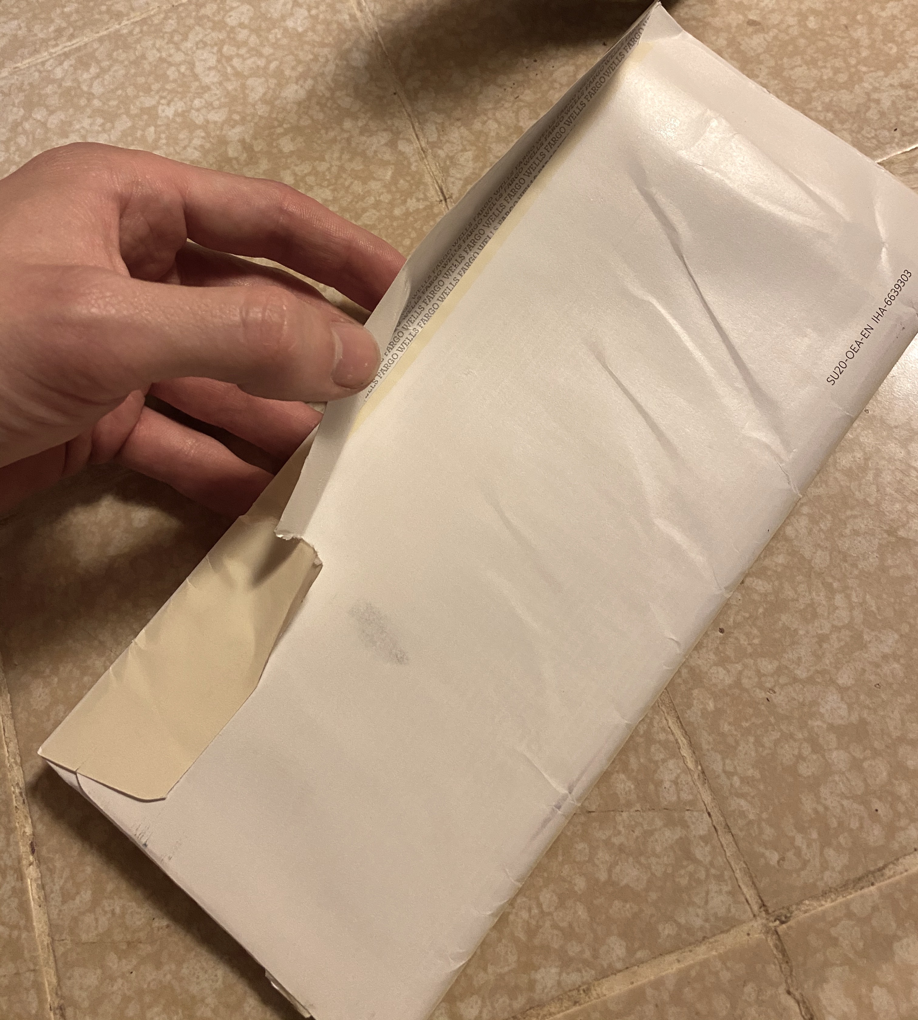
This was around when I was expecting a new credit card, so I was worried. I knew I needed some protection against tampering or theft.
There are lots of options to protect your mail, like having important mail sent to a local drug store for ID pickup or forwarding your mail to a PO box, but having to drive somewhere else every time you want to pick up your mail can be a real hassle. Instead, why not notify yourself whenever your mailbox is open and pick it up soon after? I thought of a quick solution to make sure I get my credit card before the thief does...
There are a lot of mailbox sensors out there, but this one was designed to be discreet: I didn't want to make the mailman/mailwoman feel uncomfortable seeing a sensor staring back at them, and I didn't want the potential thief to see it and take it. The mailbox quietly sends me a notification whenever it is opened and I run over to retrieve the mail before anybody else can.
Summary
I sense the door opening using a hall effect sensor connected to a NodeMCU. The data is sent to AdafruitIO via WiFi and an IFTTT applet responds to each update by sending my phone a notification. This was the easiest and cheapest way I could find to get a connected mailbox up and running.
Details
- Everything is on the underside of the mailbox, out of sight.
- A magnet on the mailbox door moves toward the hall effect sensor when the mailbox when it is opened.
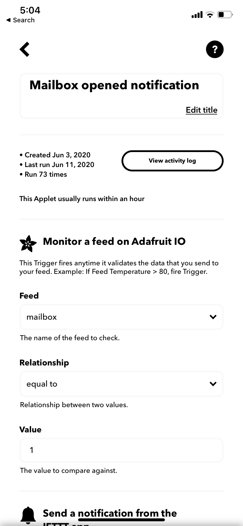
- A battery-powered NodeMCU connected to my wifi detects the hall sensor change and sends it to a "feed" on Adafruit IO.
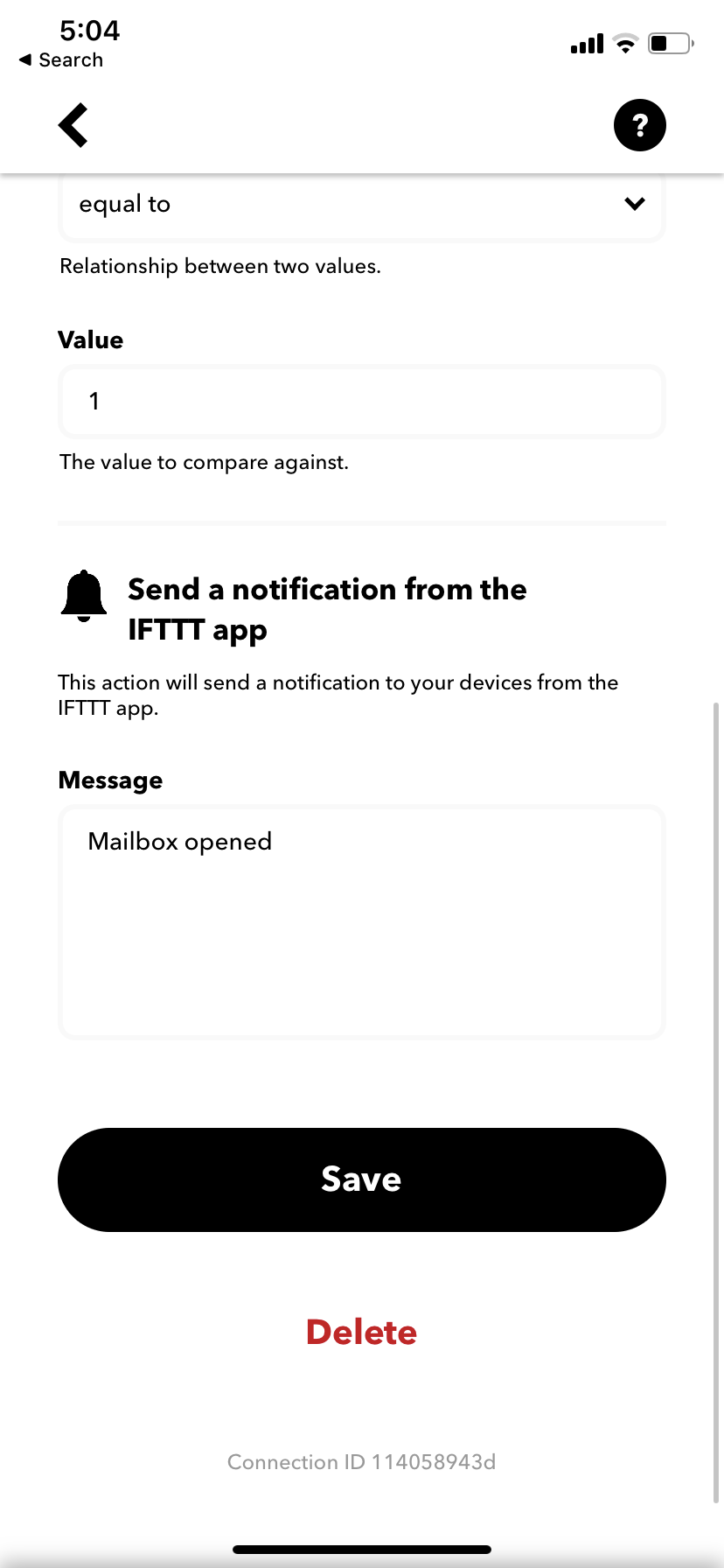
- An IFTTT applet connected to the Adafruit IO feed responds to the update by pushing a notification to the IFTTT app on my phone.
- If the battery is low, a separate IFTTT applet sends me a notification using the same pipeline as above.
Results
This is a quick-and-dirty project to get the job done, so I used whatever was lying around my house to make it work.
Construction
I used a metal L-bracket and a small piece of wood to fix the hall effect breakout board to the mailbox post as shown below.
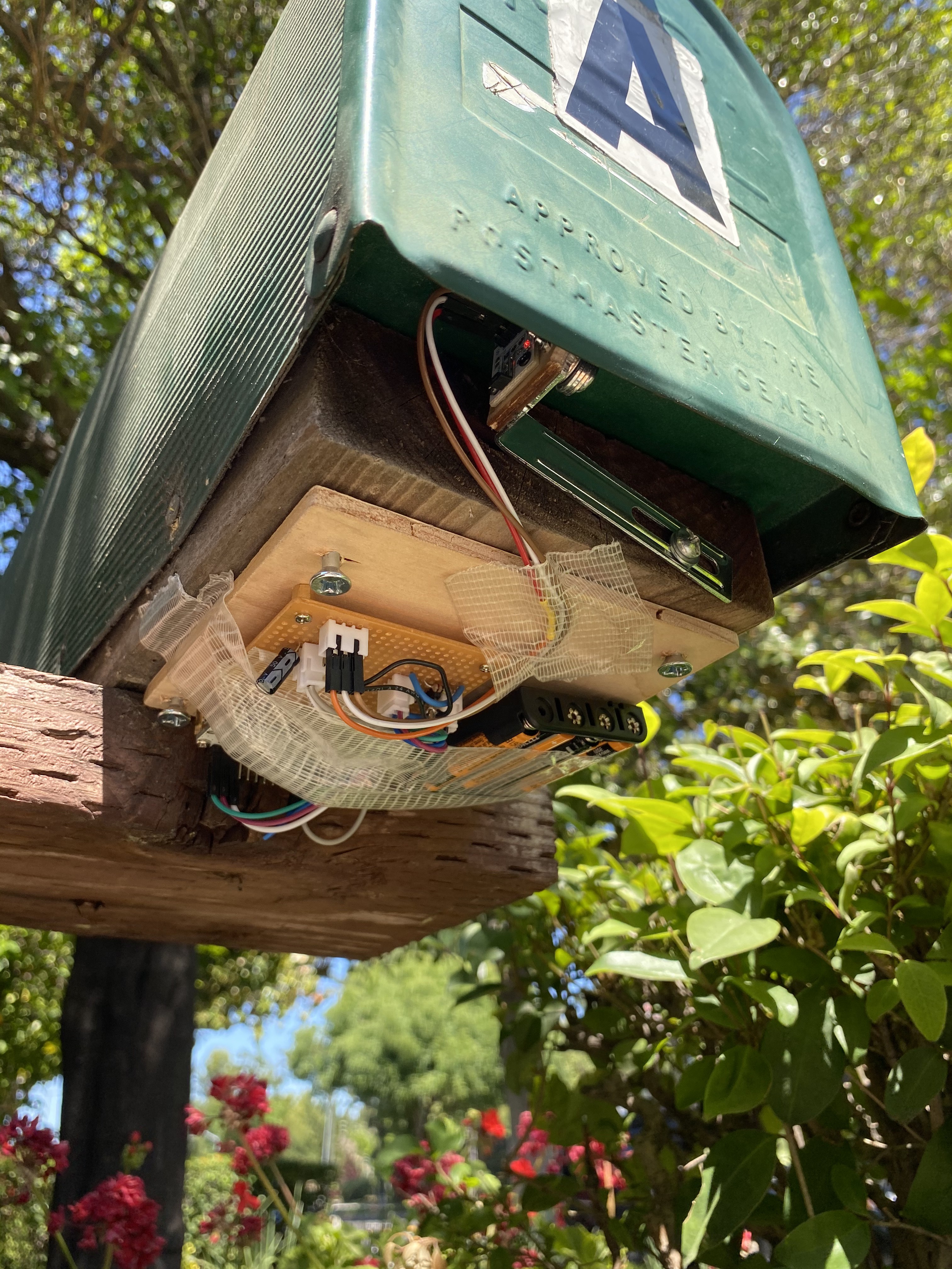
All the electronics were attached to a piece of plywood that I drilled to the bottom of the mailbox. The breadboard and NodeMCU are attached via standard pcb standoffs and the battery with tape. I used more tape to conceal all of the wires below the mailbox, since they were a little long.
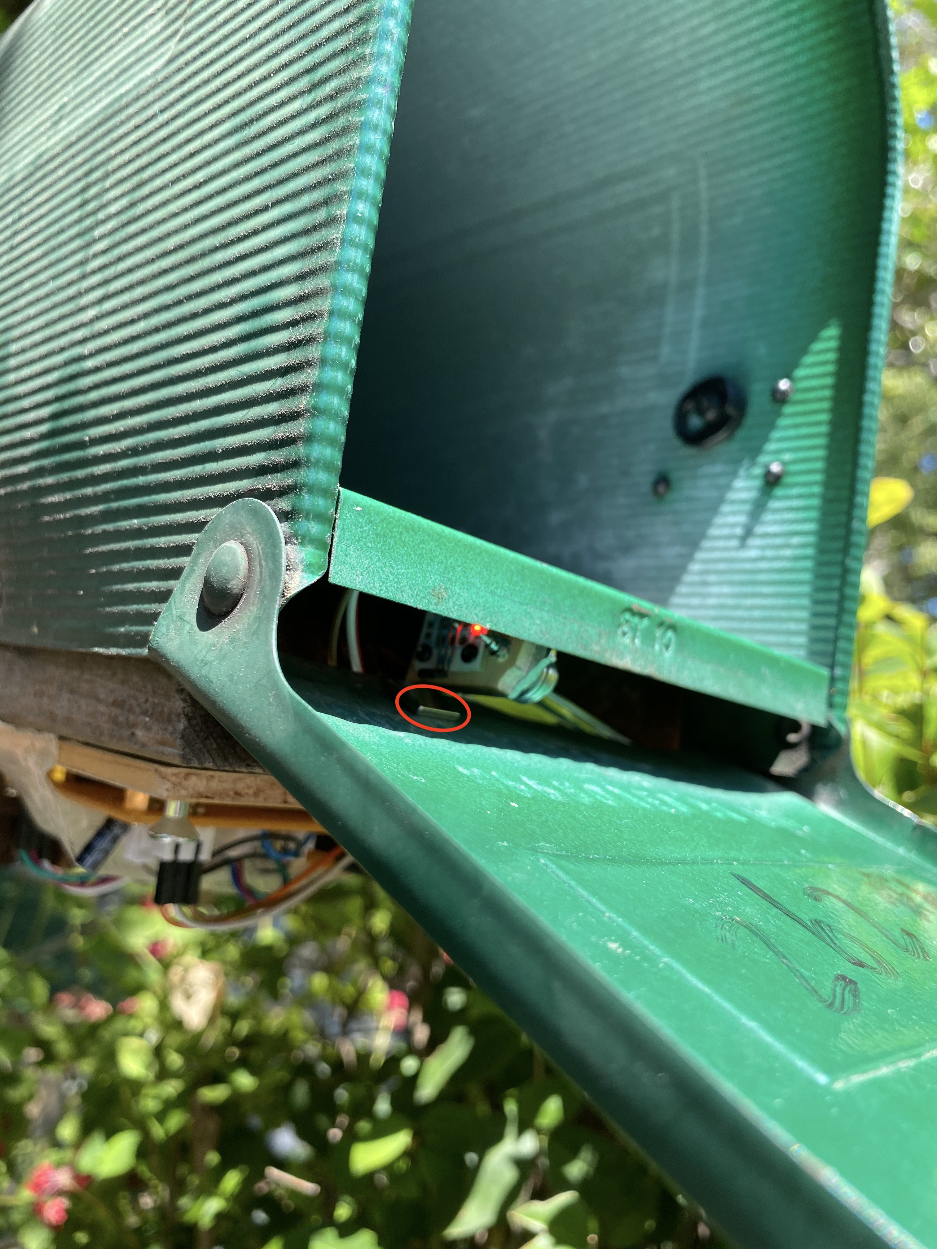
You can see above that the magnet approaches the hall sensor when the mailbox door is open. The sensor itself has a large hysteresis band to avoid reporting a bouncy signal.
Connectivity

Latency
I initially expected the app would respond in seconds, but I quickly found that unrealistic. The delays are approximately (NodeMCU -> AdafruitIO = 2s), (AdafruitIO -> IFTTT = up to an hour), and (IFTTT -> push notification = a few seconds. The largest variance is between AdafruitIO and IFTTT. After a little [online research](https://www.quora.com/Why-is-IFTTT-so-slow-to-react-to-triggers), it seems that IFTTT uses polling, which can take on the order of 15 minutes. The trick is to use non-polling mechanisms, like "webhooks." That will be my next step.
Notes
- IFTTT sometimes missed events from AdafruitIO. I don't know which side the bug was on.
- Power: my first system was a battery hog. I went from a VCC of 6.3 to 5.8 V in 30 min. I could tell that the bulk of the power consumption was from the ESP8266 itself, since the module was warm. I needed a way to poll the sensor at 2 Hz (at least) while burning less power. My solution was the following state machine:
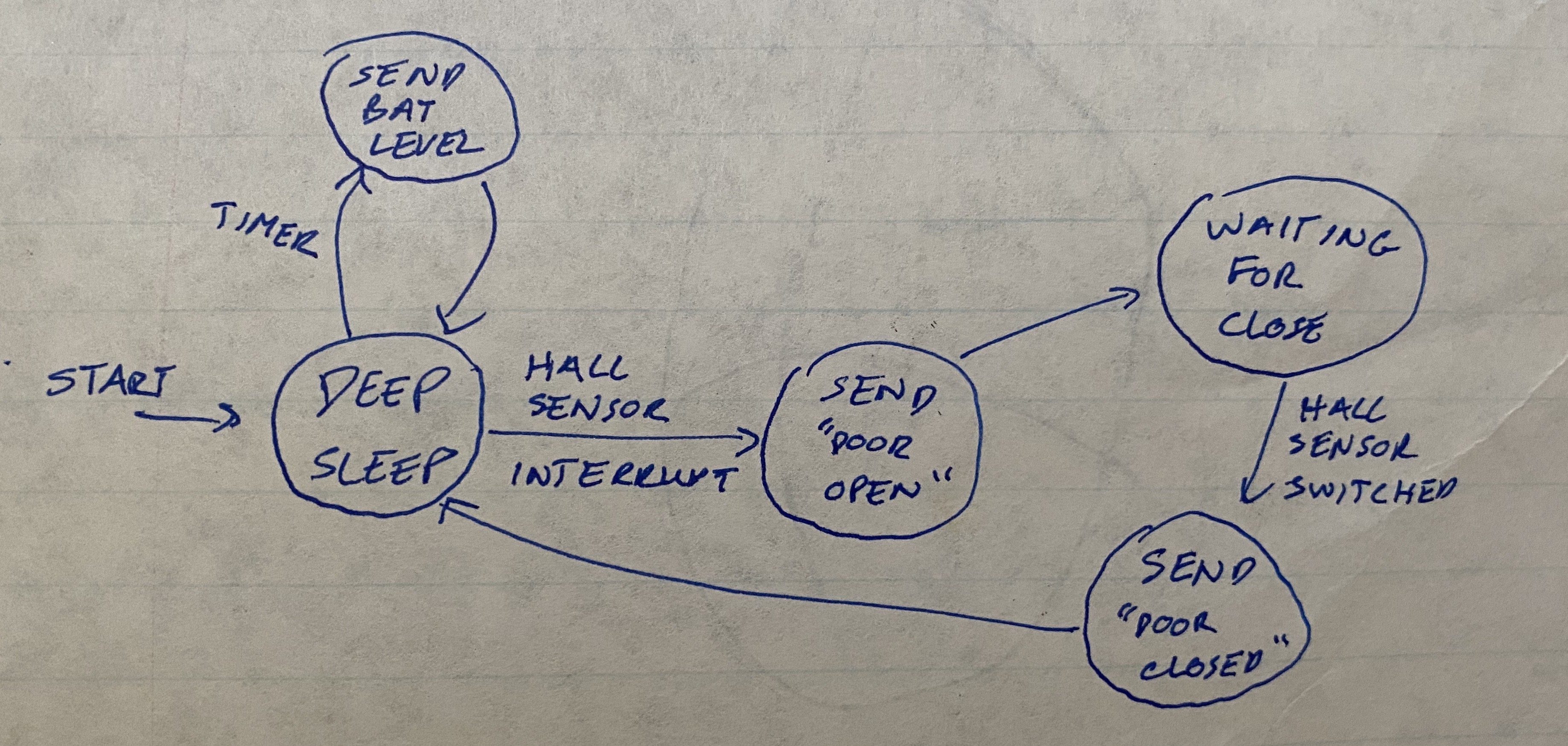
- The hall sensor interrupt required a circuit that would generate a pulse on the RST pin when the hall sensor went active low. The problem is that, when using the timer to wake, GPIO16 holds the RST pin high with low impedance to VDD during deep sleep. It would be easy to just remove the timer from deep sleep, so that's what I did.
- I use a capacitor to AC-couple the hall effect sensor to the RST pin, thereby generating a pulse on RST when the sensor goes LOW.