 Vincent
Today I took the big dip in opening up the actual Pip-Boy kit and looking at the parts in-hand.
I've been theorycrafting for a while now, but no plan survives the real world, right?
There's also this tendency I have to over- or under-estimate the size of an object when I buy it online.
Which, for that exact reason, is why I decided to use a grid for the following pictures. These squares are 1x1cm.
As discussed in My Plan, the Rad Module would indeed be the Raddest of modules, at it would house the Artemis Nano board, along with a Motor Driver and an X27 motor. I don't have the X27 motors in hand, but I could already do some preliminary fitting with the stuff that I had at hand.
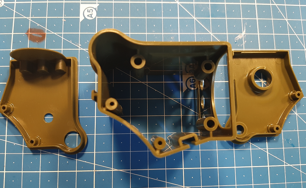
Here's an outline of the parts that make the body of the Rad Module:
 And here are (part of) the parts that will have to fit in this space:
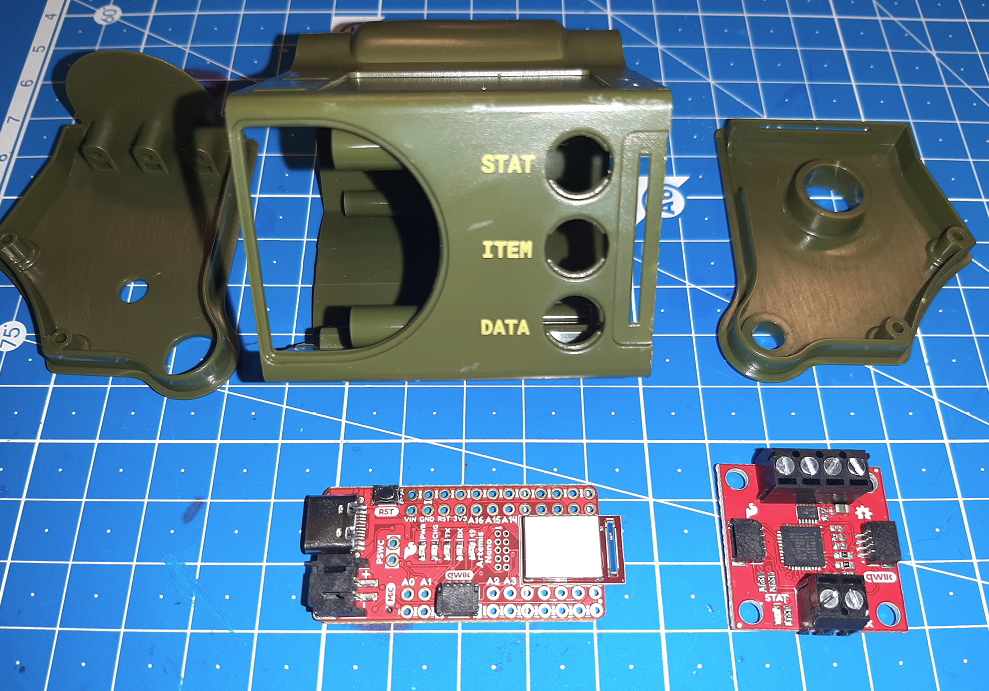 As you can see in the picture above, the Artemis Nano on the left is a pretty nice little hardware package. Aside from USB-C, it also has a regulating circuit on it, that handles the power and charging by and of a standard LiPo connector. It's said that the chip has an Real Time Clock, is Arduino compatible and can communicate over Bluetooth. (Although I did read somewhere that the supporting driver/software stack is not really finalized yet for Bluetooth, but that might have changed already).
On the right is a "Qwiic" motor driver board, (both are from Sparkfun by the way) which allows me to easily (and sturdily!) attach both boards with a tiny cable to each other without too much hassle (which is one of my goals of this project!)
If we plop the Artemis Nano in the shell, we can see there is plenty of space for it to fit:
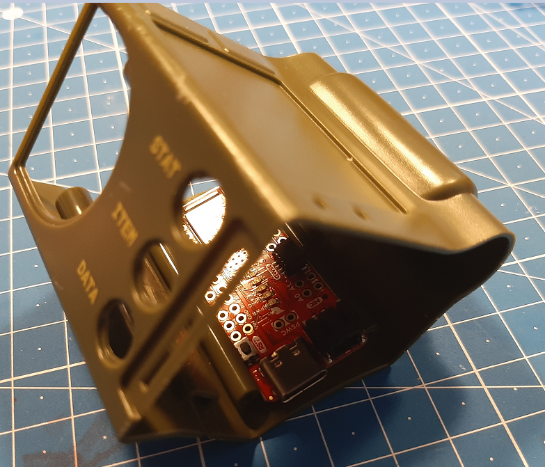 It also lines up pretty well between the screw pegs, so I can Dremel a charging hole in the side if need be!
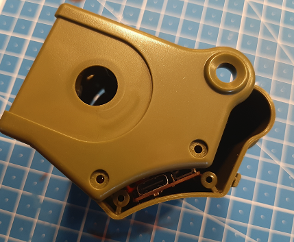 As for the Motor Board, I am pretty dependent on whether or not the X27 motor will fit. I think it might be a tight fit:
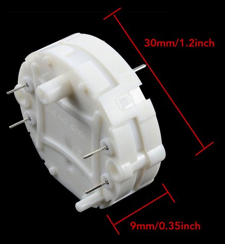 If it still fits, the other removable side might be a good place to stick the driver board on:
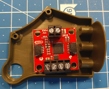
Modularity
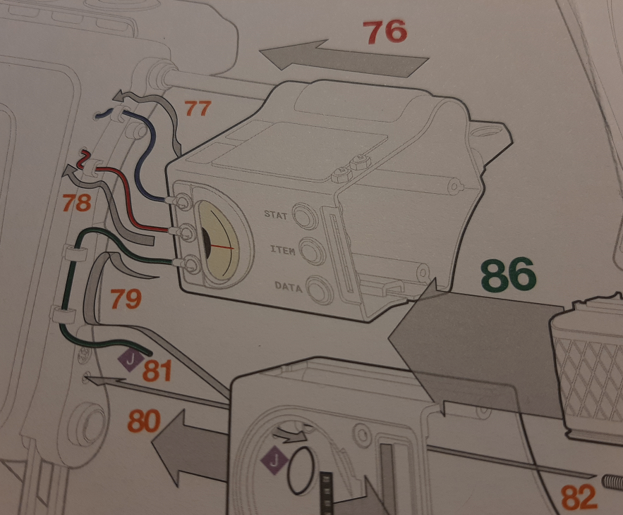
If you look at the construction manual, it shows that several wires go from the Rad Module to some other parts of the kit, which means I can potentially hide a lot of crimes if the Artemis Nano is capable of driving peripherals from other modules or parts of the Pip-Boy. If I can utilize Qwiic connections all the way, it would be pretty effortless to make the modules, well... modular! I could sleeve them in the colors of the original wires to make them look more accurate. But more wires = more bragging rights, right?
 I hope you all enjoyed this little foray into what's going on Pip-Boy wise.
That's it for the Rad Module today! Once I get the X27 motors in place and figure out how to mount it, I will see y'all back in Part 2 of the Raddest Module!
Discussions
Become a Hackaday.io Member
Create an account to leave a comment. Already have an account? Log In.