Got a couple of cool things in the mail yesterday, among other things a set of 3mm tactile switches. I asked around on Twitter for drop-in-place buttons, and the friendly people from Mouser EU spent some time trying to find the right switch for the job as well. The host of YourGeekFix found some buttons that look the part, so I ordered a couple of those just to be sure. However, after drilling out the post that holds the spring in place on the original buttons, and filing down the sides of the switches, I can safely say that I managed to turn these duds into fully functional buttons!
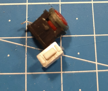
Here's a pic with one button built in, and another on the side to show its type:
These buttons are super tiny, and the rims got scuffed up a bit. Nothing a bit of Rub 'n Buff or Molotow Liquid Chrome won't fix.
Next up, knobs!
I ordered some Bakelite dial knobs, in the hope to spice up the side-dial of the Rad-Meter. I'm still on the fence whether or not I go for the original or the more industrial-looking knob. Both of them are very easy to install. We'll see when the rest gets done. I got 10 of 'em! And yeah I manhandle my parts. Call it "Natural Weathering" ;).
All that's left for the Rad-Module now is:
Print out Rad-Meter Waterslide Decal to put on the VU-Meter.
Find a way to wire all the buttons and dials together so I only have a couple of wires going out of the module. Perhaps a mux should be installed? Not sure.
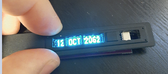
So I spent the better half of my weekend fidgeting with the OLEDs and the HoloTape Module! I initially bought some I2C OLEDs with their headers already attached from AliExpress, and my skills at de-soldering these pins are abysmal to say the worst. Furthermore, me manhandling these small pieces of electronics have already cost some of these (albeit cheap) screens to die from having their ribbon cable ripped from their pads. Yeah... So I ordered a couple (5) new ones from AliExpress that didn't have those pins pre-installed. I tried adding some JST connectors, but those ended up being to bully. 90 degree pins with dupont connectors also didn't fit, so I spent a good couple of minutes soldering wires to the OLEDS.
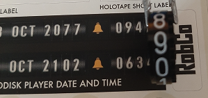
I removed the OLED screens from their adhesive backing and spaced them out so both of the screens would touch the back of the plastic display. This way I could cover almost all of the holes for the date/time display.
After I was sufficiently happy with the approach I took, I used electrical tape to protect the soldering points, and provide some structural support for the wires. I then hot-glued it all together to a singular module with 8 wires sticking out. Ideally I would have daisy-chained them with Qwiic connectors, but those connectors added too much bulk so I wouldn't be able to get the OLEDs to line up properly.
The Fitting Now that I have my "OLED Module" done (oh I just remember I have to test the screens!), I had to find a way to put it all in the module without interfering with the tape ejection mechanism. After a couple of fittings and looking at the manual, I decided to cut some holes in the bottom, in some raised parts on the bottom of the module:
The space on the lower right of the picture is going to be decorated with a black/yellow warning decal, so I thought it would also be aesthetically fitting for wires to come out on both sides. Threading the wire bundle will hopefully also provide a strain relief on the OLED display wire connections, as it's being friction-locked in place. Here's the result: I will have to hide the crimes a bit, but that's where paint and Milliput come in ;). Here is a better view of how I put the wires in: They come out the back, and hopefully do not interfere with the latching mechanism. I couldn't deduce from the manual if those lips on top were required for it to keep hold on something, so I drilled holes to the side of them. You might notice that the colors of the wires are inverted, but that is because one of the OLEDs is upside-down in order to fit against the other OLED screen. They are color coded, so I know which I2C pads I need to solder ;).
Next is to find out whether or not I would need to solder in an I2C multiplexer in between the Artemis Nano, or if I can address multiple I2C ports(? or are they connections? I am new to this) on the board. Both OLED screens have the same address and are not able to be changed via hardware. I guess a mux is the only option here, should the Artemis Nano not allow any of that.
Well, as I just reminded myself to test the screens, I think that's all for now as far as the HoloTape Module is concerned. Stay tuned for more updates later!
So the whole X27 idea is out of the window, really. In one of my purchasing blizzards from AliExpress, I found a VU meter with just the right dimensions. Using some code I found online, I managed to get the thing working on an Arduino Uno. Using two dials I managed to determine the max value and the vibration values. This looks way better than my dingy old X27 motor!
I then got to work in trying to fit the whole thing into the Rad Module. I bought 2 of them, so I sacrificed one to see how far I could cut it down. That way I'd have enough space in the Rad Module for the Artemis Nano and other boards.
...I ended up totally destroying the 1st one but at least I had an understanding of how it all worked. I then asked my AliExpress supplier how I could open the case so I could change the graphic on the dial to a more Pip-Boy accurate one. They sent me a video that showed someone bascially pulling the top off, so that was more simple than I thought. The plastic topped screw in the middle doesn't seem to do anything.
After some testing with fitting and cutting away some internal supports, I decided to just go for the easy route and just flip the dial the "wrong way round", as that would provide a working dial and did not require me to re-engineer the whole module. It will mean I will most likely have to put the Artemis Nano somewhere else. I think I'll add it above the screen, in the Red Button Module:
Perhaps I can then use the button for something related to the Artemis Nano's functions. Maybe even use it to reset the clock on the OLED displays for the HoloTape Module!
All that is left is to find myself an off-the-shelf 3 button array that is small enough to fit in the space next to the VU meter, or design one of my own. Those buttons are real tiny, so I hope I can either find a good match for them, or reuse the dummy buttons from the kit.
As a final note, here's a pic of the Rad Module with the VU meter in place:
Looking good, huh? Well, that's it for the Rad Module for now. Hope you enjoy these logs!
I was on the fence of buying this thing, as it costs almost as much as the whole PipBoy kit, but I managed to find a good discount coupon to save some bucks. The build was fun, and the speaker works pretty well. However, it needs upgrades of course!
We were already going to buy some stuff online at Ikea, and I saw they sell this wonderfully cheap Qi charger. The LIVBOJ. Similar stuff at Aliexpress cost about the same price, and somehow I trust Ikea a bit more when it comes to consumer electronics. Well, let's put that LIVBOJ into a PIPBOJ charger stand! For anyone else trying this, there are some screws below the rubber feet that allow ease of access. I only found this out after several minutes of trying to wrench the top off with an iFixit kit.
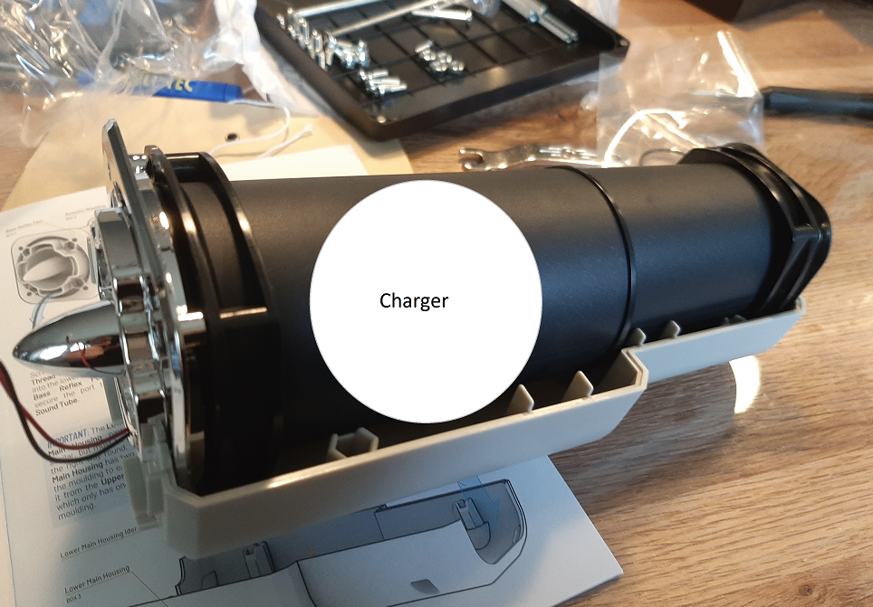
I do hope the module fits, but I can always wire the charging coil up to some longer wires. Dimensionally I think it could fit inside the cuff holder.
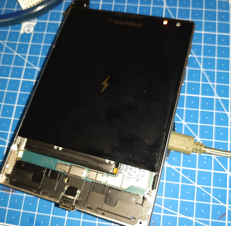
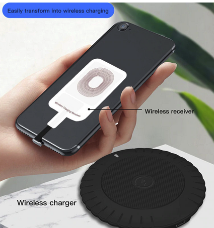
My idea is to put this module inside the holder for the PipBoy, so that it can wirelessly charge the BlackBerry Passport when needed. I did find out that the BlackBerry passport I've got doesn't do wireless charging. Fear not, AliExpress to the rescue! With some stickers that you can plug into your phone's USB port to add wireless chargint
Seems dodgy at first, but makes sense. It will also have 0 impact on aesthetics, as the phone will be tucked in the cuff anyways. I will have to find a way to make it fit though, but I think the straight walls will help with that. Might just have to cut some fins off:
Hey all, it's been a while since there was a new Project Log. I've been fiddling around with the Holotape Module to see if I can get the OLEDs to work.
The good news:
The OLEDs are a perfect fit for the module.
I can drive them easily from the Artemis Nano.
I got the clock to use the Artemis Nano's RTC module!
The bad news:
These OLEDS have a fixed I2C address so I can't daisy chain them without having to put a I2C multiplexer in between them (which doesn't fit anywhere). Plan B is to just use different SDA and SCL pins on the Artemis Nano for the screens and see how that goes. I do wish to keep it as modular as possible, so perhaps do a break-out plug in between... not sure.
One OLED screen doesn't cover all the holes. One screen can cover the whole "date", but no screen fits between the first one and the gap for the "time" hole:
2 OLEDs pushed together gives a gap in the middle of the "year" hole. I might be able to alleviate this with some dark tinted transparent plastic in front of the holes. The light will shine through regardless.
I got to wait on some new OLED screens as I kinda destroyed a couple trying to fit them in, and soldering wires to them. I learned from that mistake and bought some Grove and JST connector kits to make sure I just wire connectors tot those pins. However, the pins are not 1:1 compliant with the Qwiic or Grove standard, so I've got some rewiring of plugs to do.
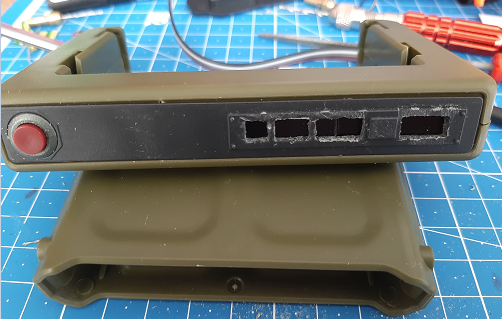
Lastly, the main reason for the title, is that I've found the perfect drop-in replacement for the top red button on the Pip-Boy:
It's the LP0125CMKW01C - Pushbutton Switch 1CO ON-(ON) Black / Red, by NKK. I only had to snip off an alignment peg below the rim of the button for it to snap into place. The click it gives is amazing, and it fits like a glove! The button is a bit brighter red than the original, but it's on point! The original button uses a spring on a peg I believe, so I cut the peg, and the button fits perfectly.
The next step is to figure out what to do with the button! If I can find a way to remotely start the BlackBerry, this would be the excellent button to utilize for that function. Time to put on the thinking cap!
The next project log will cover the Pip Boy Stand I bought recently, and my plans for that. Stay tuned!
As promised, this is going to be THE RADDEST module of them all, so here's a double whammy! Two logs in one day!
As I was scouring the Internet for some good Geiger Counter sounds, I stumbled upon this wonderful piece of code by [Samuelvdv] who uses a proprietary indoor positioning Arduino shield to make the "Geiger counter" go off when approaching specific locations. If I could use (part of) this code to perhaps track a BLE beacon, that would allow me to create "radioactive" props for use with the Pip Boy. In his article, he also links to an older project by [Jeff Haas] that uses a 1 Ohm speaker. Luck has it, I ordered a couple of those for another project of mine! I managed to test out the sounds the "Geiger counter" makes. The speakers are super tiny, and only uses up one GPIO-pin and connects to GND. The sound resonates pretty well in the Rad Module, so I think we can also consider the sound part of it all a big success! Now to cobble and code everything together!
I'm posting the code here with attribution just so I don't lose it myself ;).
// Geiger Counter - simulated sound effect by Jeff Haas
// Source: https://www.instructables.com/id/How-To-Make-A-Fake-Geiger-Counter/// Connections:// Arduino Pin 10 is toggled to create audio sound effect and goes to LM386 amp// Arduino Pin 9 is the activate button, which must have a pull-up resistor on it// An LED (which is optional) can connect to Pin 8 (and needs a current-limiting resistor and connection to ground)// FINAL port on 5/25/2012#include<inttypes.h>#include<avr/io.h>#include<avr/interrupt.h>#include<avr/sleep.h>#include<stdlib.h>// #include "iocompat2.h" Not needed in Arduino environment// #include "pin_macros.h" Not needed in Arduino environment#define INIT_TIMER_COMP 0xffff #define LOWBYTE(val) ((uint8_t)((val) & 0xff)) #define HIGHBYTE(val) ((uint8_t)(((val) & 0xff00) >> 8)) #define B_DATA_PORT_MASK (_BV(DDB0)) intfoo(void){
return2;
}
voidtoggle_b2(void){
PORTB ^= _BV(PORTB2);
}
voidled_out(uint8_t val){
unsignedchar tval;
tval = PORTB & _BV(PORTB2);
tval |= ~val & B_DATA_PORT_MASK;
PORTB = tval;
}
voidstop_timer1(void){
TCCR1B = TCCR1B & ~(_BV(CS10) | _BV(CS11) | _BV(CS12));
}
voidstart_timer1(void){
TCCR1B |= _BV(WGM12);
TCCR1B |= _BV(CS12); /* clock prescale divide by 8 */// Original non-Arduino value was CS11, in Arduino environment, set to (CS12), which is 256.
}
ISR (TIMER1_OVF_vect)
{
led_out(0x1);
}
voidset_compare_timer1(uint16_t val){
OCR1AH = HIGHBYTE(val);
OCR1AL = LOWBYTE(val);
}
typedefenum {
UP,
DOWN,
} SVAL;
#define INITSHIFT 0 int sit = (5<<INITSHIFT);
int shift = INITSHIFT;
ISR (TIMER1_COMPA_vect)
{
staticunsignedint delay = 0;
static SVAL state = DOWN;
int in = PINB;
cli();
stop_timer1();
toggle_b2();
if (in & 0x2) {
state = DOWN;
led_out(0);
} else {
state = UP;
led_out(1);
}
delay = (rand() & 0xDEA8); // Maximum length of the delay between clicks, a random number. Original value was 0xffff (65536).if (delay < 0x40) {
delay = 0x40;
}
if (sit-- <= 0) {
switch (shift) {
case0:
if (state == UP) {
shift = 2;
sit = (5);
} else {
shift = 0;
sit = 1;
}
break;
case1:
case2:
if (state == UP) {
shift = 3;
sit = 1;
} else {
sit = 1;
shift = 0;
}
break;
case3:
case4:
if (state == UP) {
sit = 1;
shift = 3;
} else {
sit = (10);
shift = 1;
}
break;
}
}
if (shift == 0) {
set_compare_timer1(delay<<2);
} else {
set_compare_timer1(delay>>shift);
}
start_timer1();
led_out(shift);
sei();
}
voidioinit(void){
DDRB = B_DATA_PORT_MASK | _BV(DDB2);
PORTB = 0;
TCCR1A = 0;
TCCR1B = 0;
set_compare_timer1(0x4000);
TCCR1A = 0;
TCCR1B |= _BV(WGM12);
TCCR1B |= _BV(CS11);
}
#define JVAL 100000;intmain(void){
ioinit ();
srandom(0x12345678);
set_sleep_mode(SLEEP_MODE_IDLE);
TIMSK1 = _BV (OCIE1A);
cli();
sei ();
sleep_enable();
sei();
for (;;) {
sleep_cpu();
}
return (0);
}
The X27 dial gauge motors came in this week, a whole box of them (as I tend to break stuff ;) )!
Steering the motors
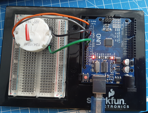
Thanks to the SwitecX25 library by [guyc] setting up the X27 was pretty easy. Seems I only need 4 pins to power this little motor, so I think we can do away with the Qwiic motor driver and power it from the Artemis directly! I'll dry run most on the Arduino Uno for now though.
Using the demo code, when I select a number from 0 to 944 (give or take) in the terminal prompt, the dial spins round. But I've yet to figure out some code to scale it to the arc I want the dial to move into. It also seems to be quite erratic, as it not always seems to jump to a (for me) logical place on the dial. The dial will have to respond to "teh Geigurz" I will be faking by some other means, so accuracy is not that important but it would be nice for it to actually gauge something semi-correctly. However, as a proof of concept, I have managed to get the dial to spin, so I got that goin’ for me, which is nice. I used part of a Gundam model kit's sprue/runner as a dial gauge. I'll try and whittle it down to a finer point going forward.
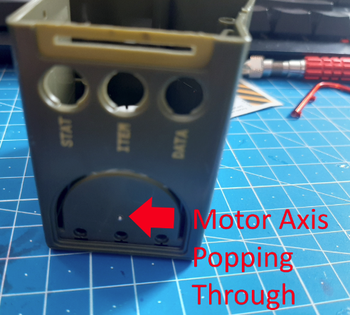
Fitting the dial motor
I was afraid the motor would have been too big to fit inside of the Rad Module, but give or take some plastic struts that may or may not be removed, the dial motor fits pretty well, as you can see in the pictures below:
As you can see, I think it will fit pretty well if I remove (part of) the screw struts.
Might even put some neodymium magnets in the top of the holes so I can just use magnets to affix the side plates. I'll have to solder and reinforce the motor pins to some cables, but those can be routed to the Artemis Nano directly, so skipping on the motor driver board will save me some space in there.
The next step is going to be finding a way to produce some real Geiger counter noises when the dial is moving, and I think I've got just the thing for that! See you in the next Project Log!
Good news everyone! The OLED displays got in, and I couldn't help but do a proof of concept fitting test. I hooked the OLED up to an Arduino Uno, as I only have 1 Artemis Nano board (and I don't want to mess that one up so early in the project!). I downloaded the Adafruit libraries for this thing, and lo and behold the screen fit and worked!
I disassembled the Holotape Deck and cut out an initial hole for the OLED to show through. Here's the initial quick & dirty result:
As you can see, there's plenty of room up and downwards of the enclosure to fit in the OLED display. Unfortunately the display is not long enough to cover all of the digits for the timer/counter, so I might have to fit in two displays (I do hope I can drive two of them at the same time!). As for pixel real-estate, you can see how many characters I can cram in there. I hope, with some elbow grease I can design a nice rolling counter animation, but I will settle on a digital clock that tells the time correctly!
Since I used the Arduino UNO with some DuPont connectors, there's some fitting issues. I think if I directly solder wires to the pins and drill some hole for the wires to go through, it might be a good fit. It will all depend on whether or not I can drive two screens with one Artemis Nano. I did find the code for it on the Adafruit's forums, so there's that:
#include<Wire.h>#include<Adafruit_SSD1306.h>#define SCREEN_WIDTH 128 // OLED display width, in pixels#define SCREEN_HEIGHT 32 // OLED display height, in pixels// Declaration for an SSD1306 display connected to I2C (SDA, SCL pins)#define OLED_RESET -1 // Reset pin # (or -1 if sharing Arduino reset pin)Adafruit_SSD1306 display(SCREEN_WIDTH, SCREEN_HEIGHT, &Wire, OLED_RESET);
Adafruit_SSD1306 display2(SCREEN_WIDTH, SCREEN_HEIGHT, &Wire, OLED_RESET);
voidsetup(){
display.begin(SSD1306_SWITCHCAPVCC, 0x3C); // Default OLED address, usually
display2.begin(SSD1306_SWITCHCAPVCC, 0x3D); // Second OLED address, via onboard jumper
display.clearDisplay();
display.setTextSize(1);
display.setTextColor(WHITE);
display.setCursor(0,0);
display.print("Display A");
display.display();
display2.clearDisplay();
display2.setTextSize(1);
display2.setTextColor(WHITE);
display2.setCursor(0,0);
display2.print("Display B");
display2.display();
}
voidloop(){
}
It does mention I2C address-changing jumpers, so I got to check if mine has these or not.
Anyways; the journey to creating a fully functional Pip-Boy has gotten a few extra miles on the meter! In the mean time I'm still waiting for the Dial Motors and LiPo batteries to arrive. As soon as I have some more information regarding any of the modules, expect a new Project Log!
So the initial plan was to source some of those mechanical roller counters (believe me, I have tried every term on AliExpress to find these!). I got them in the mail this week, and today I decided to check if this plan would hold up. Turns out the Holotape Deck is smaller than I imagined.
If you take a look at what's needed for these rollers to actually work, you can see it's never going to fit this way. And static or 'roll your own date and watch it wiggle' digits are a no-go for me.The inset at the top-right of this picture is where the holes would be to show the numbers. The whole thingamajig with the gears in the middle left is the stuff that makes those numbers roll over. There is no way I can get this to work functionally I think.
If you look at the stickers, it seems the numbers would be off in size as well: Unless I can source smaller rollers, let's hope the OLED screen(s) will fit when they come in!
 Vincent
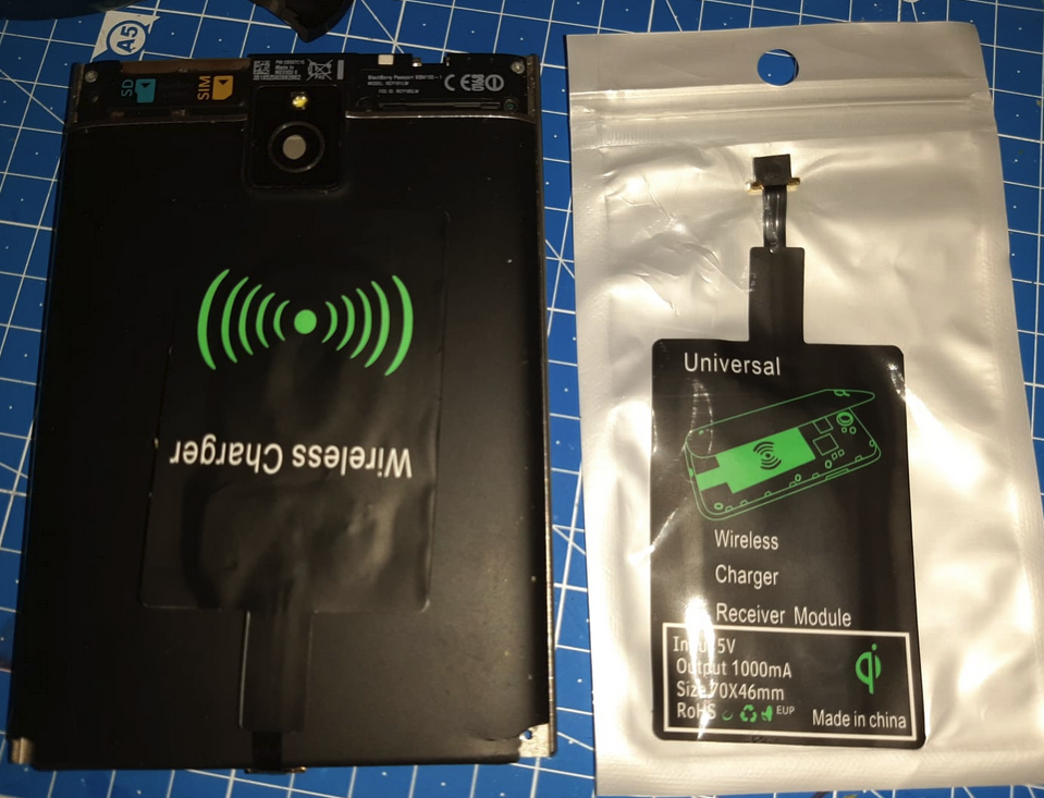 Here is a pic of the Ikea LIVBOJ I destroyed to put in the Pip Boy Stand:
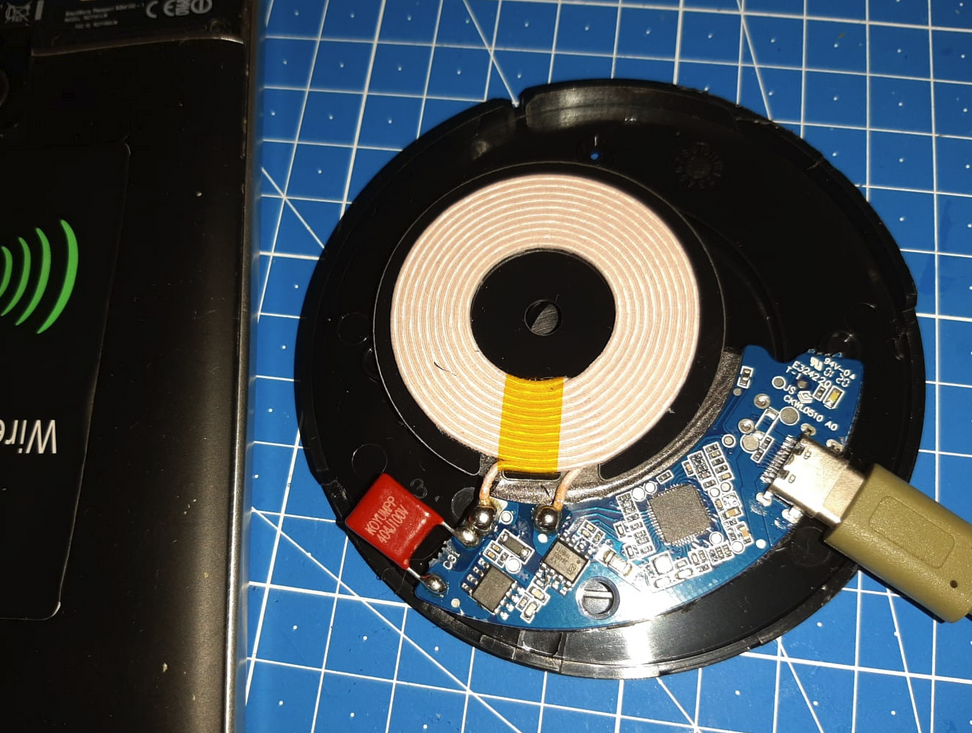
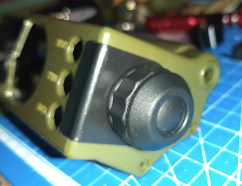
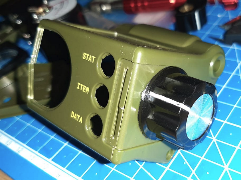 I'm still on the fence whether or not I go for the original or the more industrial-looking knob. Both of them are very easy to install. We'll see when the rest gets done. I got 10 of 'em! And yeah I manhandle my parts. Call it "Natural Weathering" ;).
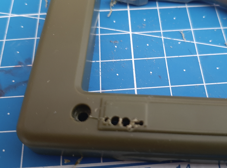 The space on the lower right of the picture is going to be decorated with a black/yellow warning decal, so I thought it would also be aesthetically fitting for wires to come out on both sides. Threading the wire bundle will hopefully also provide a strain relief on the OLED display wire connections, as it's being friction-locked in place.
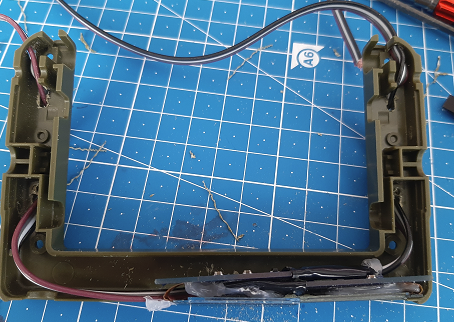
 I will have to hide the crimes a bit, but that's where paint and Milliput come in ;).
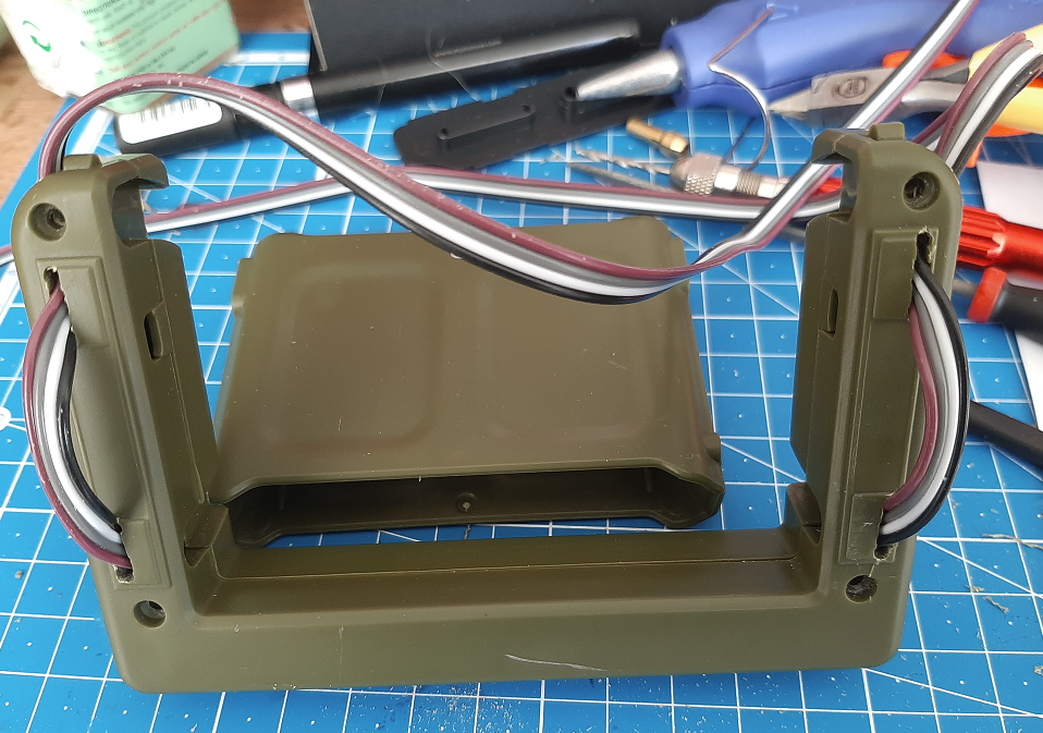 They come out the back, and hopefully do not interfere with the latching mechanism. I couldn't deduce from the manual if those lips on top were required for it to keep hold on something, so I drilled holes to the side of them. You might notice that the colors of the wires are inverted, but that is because one of the OLEDs is upside-down in order to fit against the other OLED screen. They are color coded, so I know which I2C pads I need to solder ;).
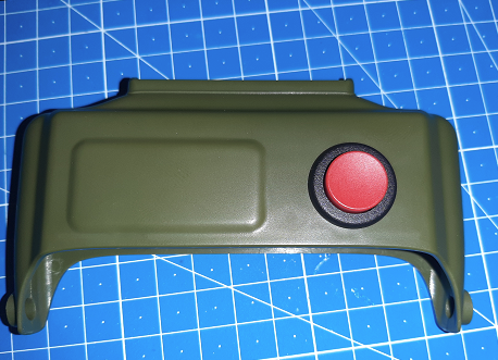
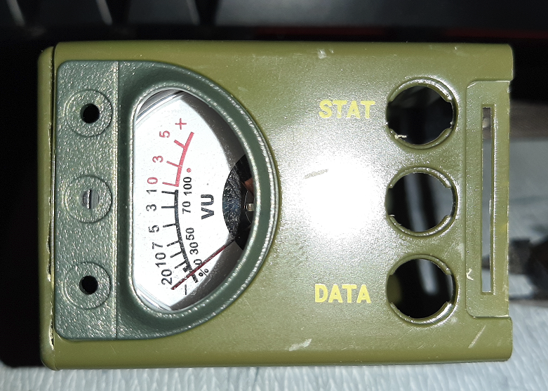 Looking good, huh? Well, that's it for the Rad Module for now. Hope you enjoy these logs!
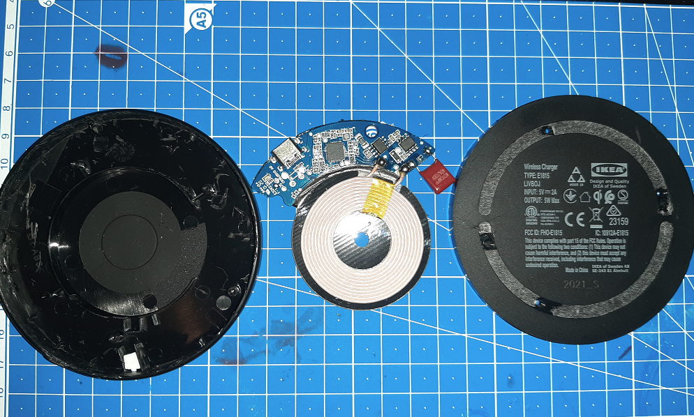
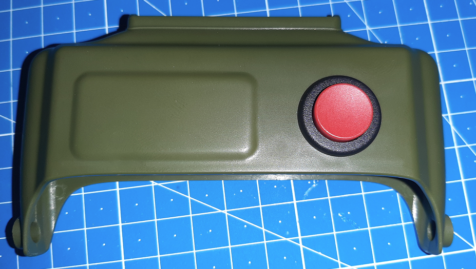 It's the LP0125CMKW01C - Pushbutton Switch 1CO ON-(ON) Black / Red, by NKK.
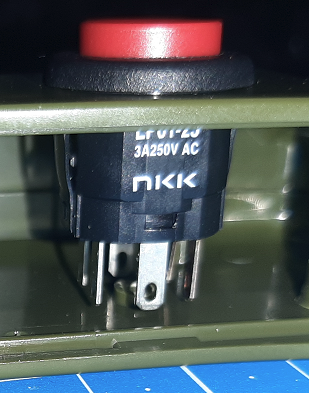
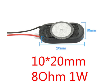 I managed to test out the sounds the "Geiger counter" makes. The speakers are super tiny, and only uses up one GPIO-pin and connects to GND.
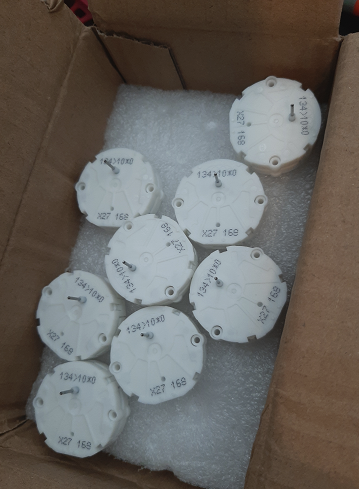
 I used part of a Gundam model kit's sprue/runner as a dial gauge. I'll try and whittle it down to a finer point going forward.
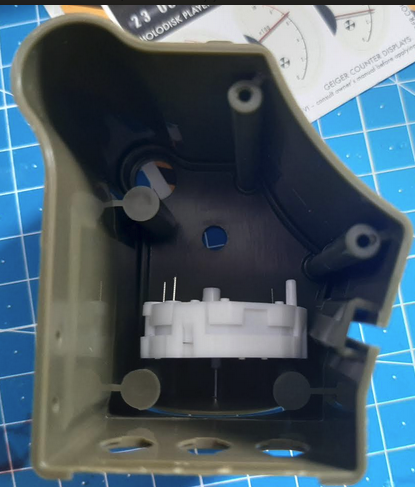
 As you can see, I think it will fit pretty well if I remove (part of) the screw struts.
 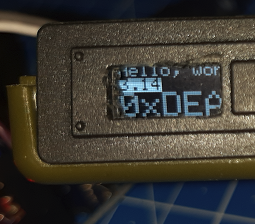 As you can see, there's plenty of room up and downwards of the enclosure to fit in the OLED display.
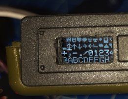 As for pixel real-estate, you can see how many characters I can cram in there. I hope, with some elbow grease I can design a nice rolling counter animation, but I will settle on a digital clock that tells the time correctly!
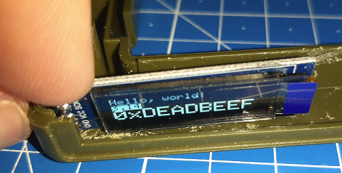 Since I used the Arduino UNO with some DuPont connectors, there's some fitting issues. I think if I directly solder wires to the pins and drill some hole for the wires to go through, it might be a good fit.
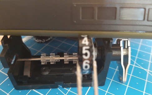 The inset at the top-right of this picture is where the holes would be to show the numbers.