 Sajiv Shah
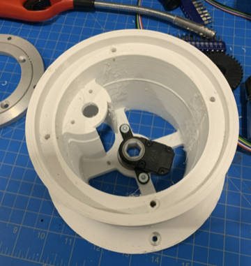
The base piece for the robotic arm is 3D printed using a 1mm nozzle and is about 8 inches wide at the max. It tapers at the base and has mounting holes to mount to a table, and also has a bearing hole in the middle, which in this image is covered by the first axis encoder. This encoder has a through bore for a hex axle, which is what I will be using as it easily indexes and does not require a set screw. The lip at the top is for a lazy Susan bearing, which will be used to attach the upper base piece. The hole towards the edge is for a DC motor, which will transfer power to the center axle using a gear.
Discussions
Become a Hackaday.io Member
Create an account to leave a comment. Already have an account? Log In.