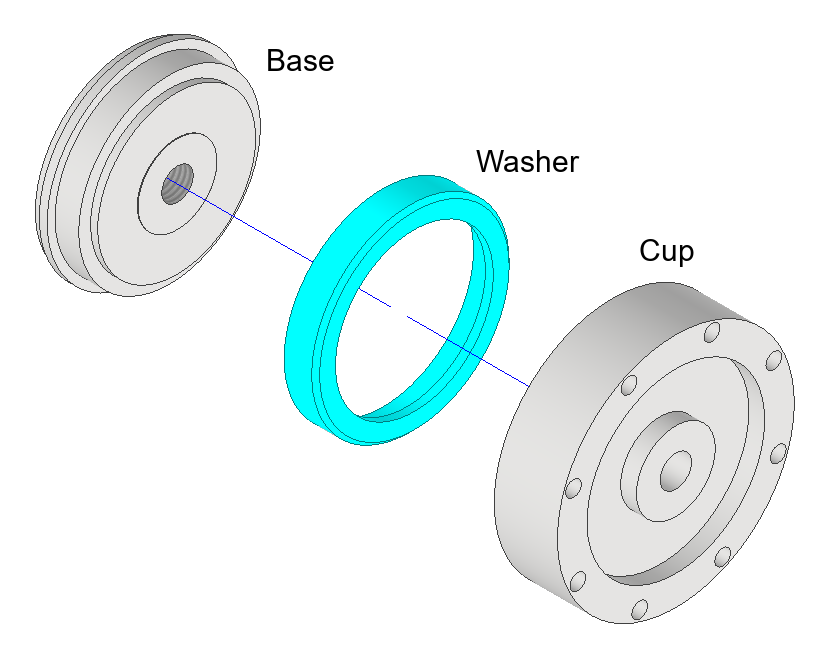
So I went and made the first prototype rotary joint. It works surprisingly well being my first attempt and I think it will certainly stand up to testing. It is very satisfying to hold and Locks very rigid when held in the hand.
The order of operations in terms of component manufacture could definitely be improved. In the first prototype there are 3 major components: The base, the washer and the cup.

There are several mating surfaces that have tight tolerances to consider. The washer must have its ID bored and be the correct length before the base is made, as the washer has its OD finished when glued to the base. This may or may not be necessary as the nylon washer will readily deform to the shape of the base, although it is definitely useful in allowing fine tuning of the washer.
The ID of the cup must be turned after the base and washer have been finished to ensure the correct fit can be achieved.
What will I change?
First, the washer should not extend to cover the end face of the base and should not be used as both a high friction material in the locked mode and a low friction material in the freely rotating mode. This will also simplify the production of the washer, with only the facing, boring and parting operations being necessary before gluing the washer to the base. Fewer critical measurements to make, fewer features to cut, simpler cleanup after glue up. Good.
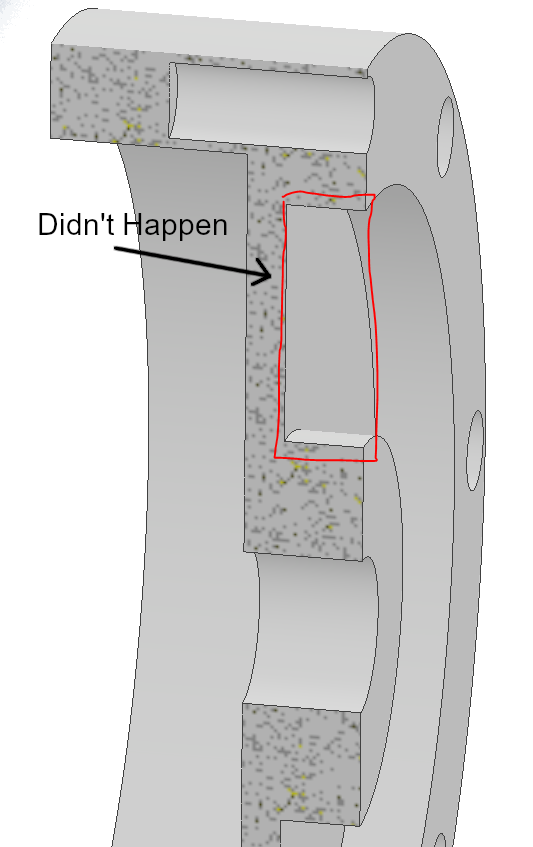
Second. I did not manage to machine the recess in the cup as shown in the picture above. I am technically capable of this machining operation, although it is not trivial, but I did not consider it necessary for testing and I could always add it later if necessary.

This recess was designed to allow the centre section to flex and make contact with the base, thereby allowing metal to metal contact and therefore good locking. This approach may have worked, at least, the aluminium could be deformed 0.05 mm when tightened with a hex key. However, this is very much missing an important engineering subtlety that will be shown in an upcoming project log. The recess may be added in future iterations for weight-saving purposes but the cup will not be allowed to contact the base near the centre of the screw in future iterations.
I also made the OD of the cup larger as the available stock allowed it and it felt right in the hand. I liked the larger overall size and I shall likely stick with this choice of OD, although I may design a smaller version in the future.
The base component was basically machined to drawing and will not likely change much in upcoming designs, although the mating face will change slightly.
 Greg Duckworth
Discussions
Become a Hackaday.io Member
Create an account to leave a comment. Already have an account? Log In.