Why didn't you tell me that this was basically a clutch?! Well, at least I found some amazing bits of information on clutch design, right the way back to some extremely early clutches in the 1900's.
Where is the project currently at?
After many hour of research and reading more than a few papers and presentations on clutch design and friction in rotary systems, I have got several more designs to test. The thing we are trying to design is fundamentally just a clutch, only its coupling two stationary systems, not two rotating systems.
I have now got a prototype for a tapered friction interface design which I will be testing in short order. In the last Project Log I detailed the limits of torque that a human could reasonably apply, which is now a parameter in the design process. The calculations that correspond to the single face contact, tapered face contact and multi-plate face contact have been done and a very predictable result has been found:
Humans are not strong enough to exert the necessary torque on a 40 mm diameter hand wheel to enable a small (< 60 mm dia.) simple clutch design to hold 180 Nm of torque, even if the clutch has a tapered face.
So, like most of the initial prototypes I make, the new tapered design of clutch is not sufficient to meet the requirements and I should have done some calculations before I wasted all that time.
But where is the fun in that?
Where are we going?
- The current designs need to be tested to confirm that the expected performance of the locking mechanism is even remotely close to the predicted performance.
- The tapered clutch design, along with the corresponding design principles and choices, needs to be documented.
- Some revisions were made to the design (Now up to version 9 of the joint design overall) so those revisions should be documented to help people avoid those mistakes in the future.
- Multi-plate clutch designs need to be documented, built and tested.
History and Background
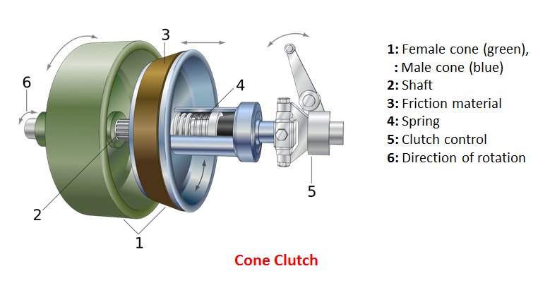
Cone Clutch
A small alteration to the flat plate clutch will increase the torque capacity for a given size of clutch, without needing to resort to a complex multi-plate clutch design. The mating faces of the clutch may be tapered, thereby increasing the contact area without increasing the overall diameter of the clutch. Care must be taken to keep the taper angle well above the self-locking angle of the material as this would make the clutch difficult to disengage.

The image shows a typical cone clutch. Image taken from here: Cone Clutch
The conical contact surface makes a considerable difference to the holding torque. For a clutch with a friction surface OD of 50 mm and ID of 45 mm, an applied force of 2.5 kN, and a friction coefficient of 1, the holding torque of a flat plate clutch is 118 Nm. For a similar conical clutch, with a taper angle of 15 degrees (30 degree included angle), the holding torque goes up to 229 Nm.
There are some limitations and negatives though. The angle of the mating components must be closely matched such that the clutch will perform well without requiring 'bedding in'. The torque is also limited by only having a single friction surface and the taper makes the action of the clutch either very strongly engaged or disengaged. The ability to set the clutch to a lower torque may be useful in this project.
Plate Clutch
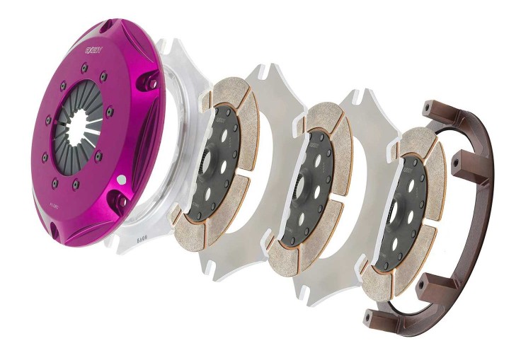
Plate clutches have not changed much (conceptually) in 100+ years, although the materials, manufacturing processes and design have seen many improvements or paradigm shifts in that time. The use of multiple clutch plates to increase the number of friction surfaces is nothing new. By stacking the plates such that half of the plates are connected to the drive-side and half to the driven-side, in an alternating fashion, the number of friction surfaces is increased. The number of friction surfaces in contact is typically Number_Of_Plates - 1, so a 7 plate clutch would have 6 friction surfaces, each only needing to handle ~1/6 of the required torque.
The dramatic increase in torque capacity comes at the cost of increased complexity, with more moving parts and an increased manufacturing burden. The increase in holding torque for a given diameter allows the clutch to be kept small and light, a requirement for smaller vehicles like motorbikes.

The image shows a multi-plate clutch with a total of 6 plates, giving 5 friction surfaces. Image taken from here: Multi-Plate Clutch
The increase in the number of friction surfaces means a corresponding increase in the amount of heat generated. This will not be a concern for our project as the clutch will be static most of the time. The two types of clutch plate must be fixed relative to different parts of the clutch, and since they alternate within the clutch assembly, this limits the ways in which the clutch can be designed. Torque is transmitted into the input clutch plate using splines in the centre and out of the output clutch plate by tabs on the exterior. Our design of clutch will be very similar.
Further Developments
I have a prototype of the simple clutch and the tapered clutch, both of which need testing. My previous calculations have showed that a tapered clutch design can fulfil the requirements, although the necessary tightening torque of the bolt in that design is almost at the limit of max torque applied by the average human female, which is too high. Further, the joint itself is quite large and difficult to mount. I will be making a multi-plate clutch to see how compact I can make the joint and how little tightening torque is required to hold the necessary 180 Nm of joint torque.
Onwards!
 Greg Duckworth
Discussions
Become a Hackaday.io Member
Create an account to leave a comment. Already have an account? Log In.