Charles Baird
So the main idea of how the eyes work uses the simulator on https://ricktu288.github.io/ray-optics/
The top row are images with the rays traced and the lower images are the observed rays. The left is a regular infinity mirror (note the column of images represented by orange dots) and the right has the lens in place. The simulator assumes an ideal lens which is why you get a nicer spacing than actually happened. If I did the project again, I would try different ones.
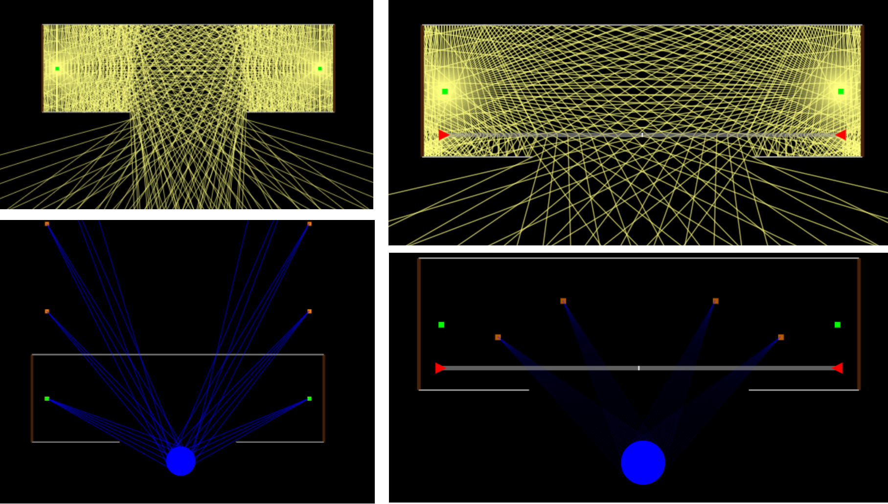
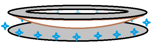
The green dot is a light from the LED strip. This is just a slice, so we only see the two across from each other and their orange images. On the bottom is the cross section of a donut cut mirror. On the top is a regular circular mirror. Here's an illustration. The LEDs are blue, the lens is white, and mirrors are gray.