 EK
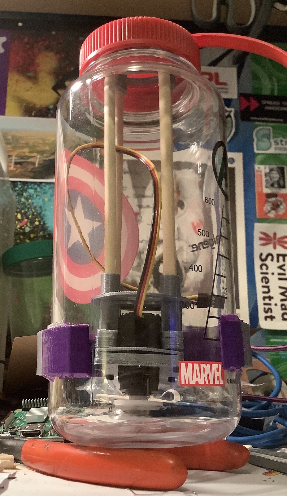
EKThe servo fits and the magnetic coupling attaches:
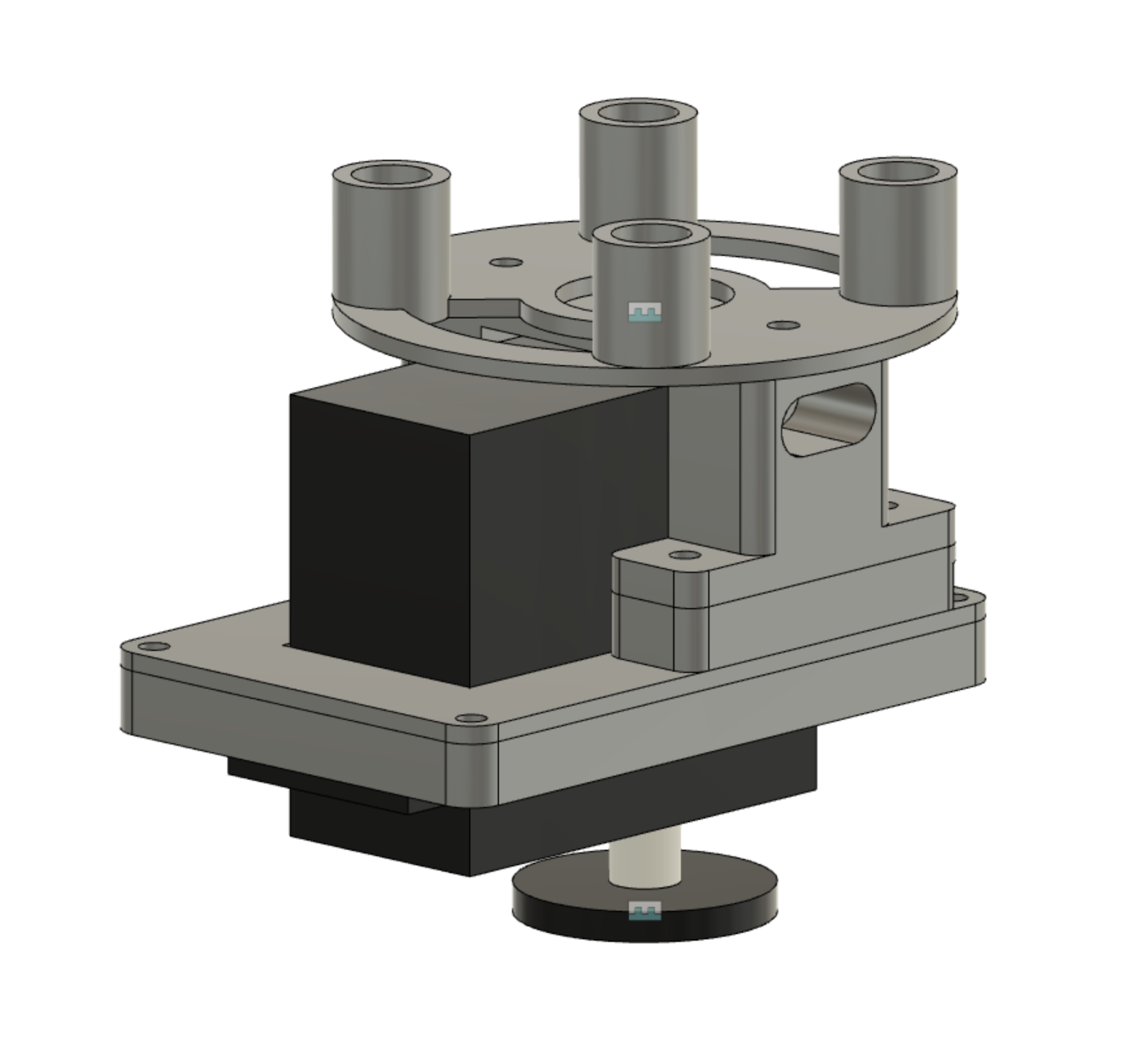
Here is what the CAD assembly of the 5 separate 3D printed pieces looks like:
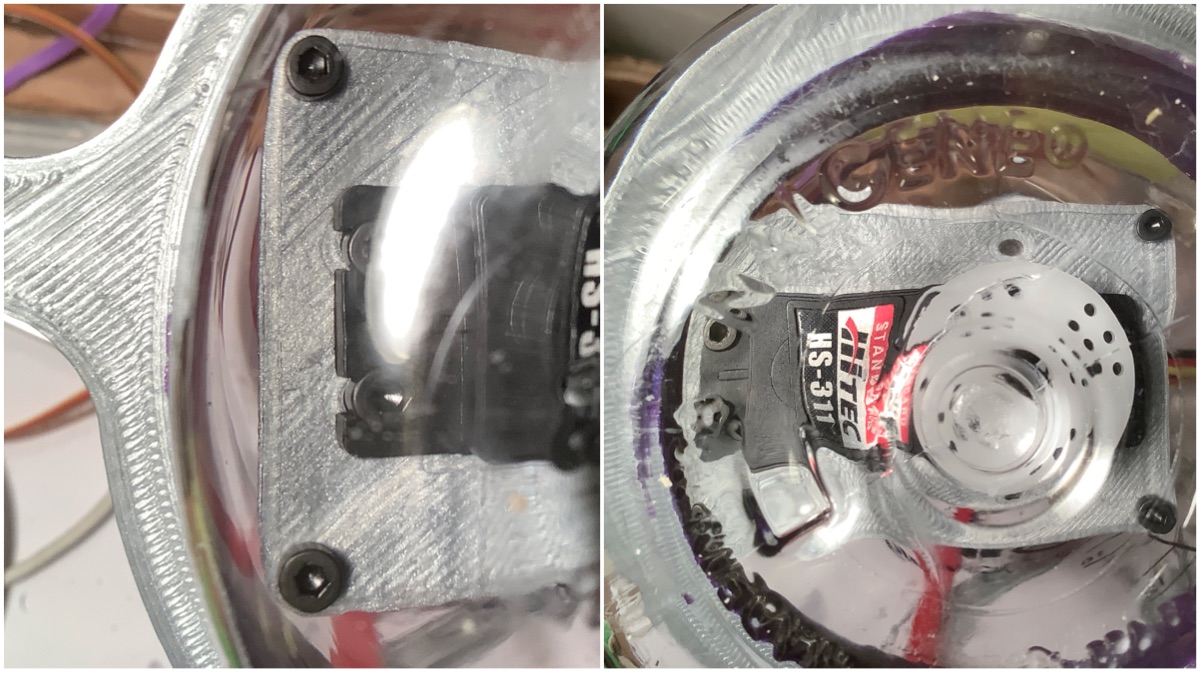
The installation process isn’t as tedious as thought it would be. You have to hold the servo by the cable in one hand, and position the magnet clamp onto the servo with your other hand holding the dowels. The tolerances of +0.4mm on each side of the servo were adequate for clearance and with no wobble.
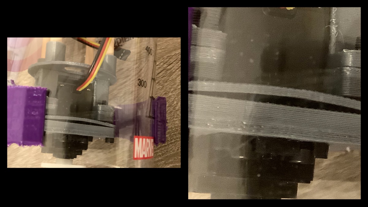
There will be some tweaks needed in the next revision. The corners of the servo bracket are touching the inner diameter of the enclosure (left). This affects the position of the servo horn to be offset (right).
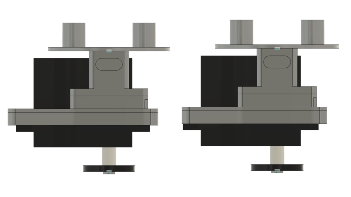
The tweak on the next revision will be very small. Can you spot the difference?
The bump from incorrect fastener diameter and length will also be solved after an order for fasteners.
Now with this gate cleared, it’s a step closer to running this experiment soon to test some of the hypothesis. The next step is the internal and external servo horn in rigid. If it struggles, then the next step is internal servo horn in flexible.
Discussions
Become a Hackaday.io Member
Create an account to leave a comment. Already have an account? Log In.