 Leonardo Ward
One of the modules that can greatly improve the original design of the Buoy (A and B) is an RTC. In this log I'll analyze the Raspberry Pi RTC Expansion Module v1.1 (Datasheet, Wiki) and explain how to adapt it to the PCB design Buoy B V1.0.
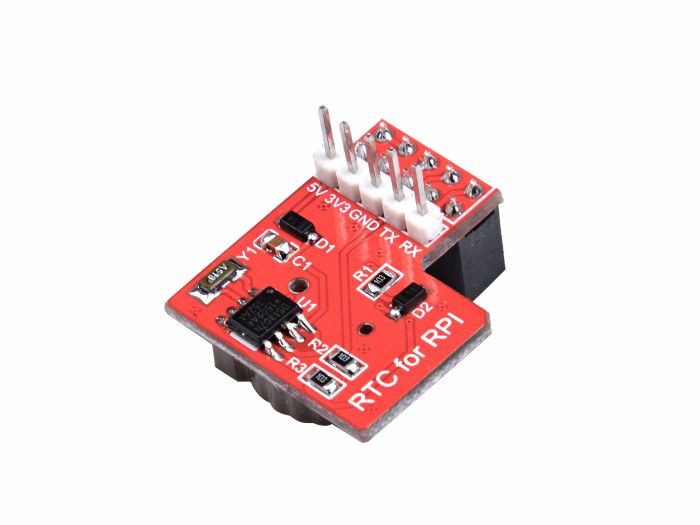
This module uses a Maxim DS1307 chip and contains a cell backup, it has been designed specifically for the Raspberry Pi.
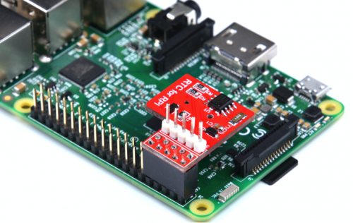
Since we want to use the Module with the ESP32 we need to understand the main connector in the module. At this moment the wiki does not contain a diagram that explains the connector, but is easy to figure out the pinout using the Raspberry PI 2 as a reference.

The RTC Module connects to the pins 1, 2, 3, 4, 5, 6, 7, 8, 9 and 10. With that information it is possible to identify the pinout of the board:

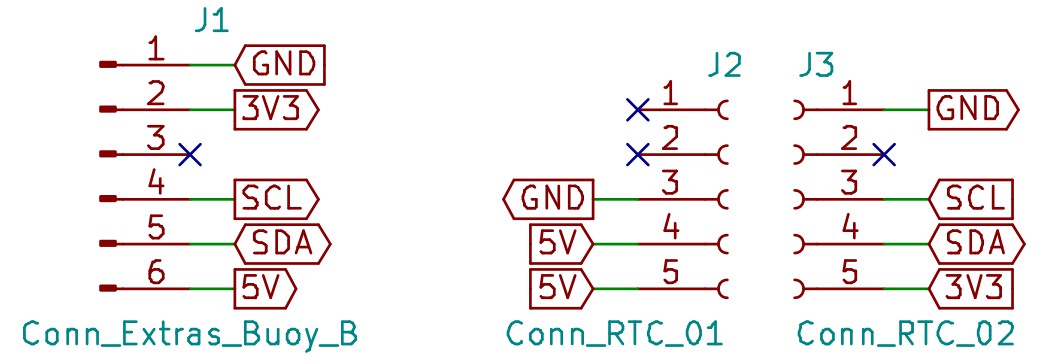
Based on the pinout, I designed a small PCB (using KiCad) used to adapt the RTC Module to the PCB Buoy B V1.0 (J7 Conn_Extras). This design can be used as an example, and can be easily replicated in a PCB breadboard.
Schematic:
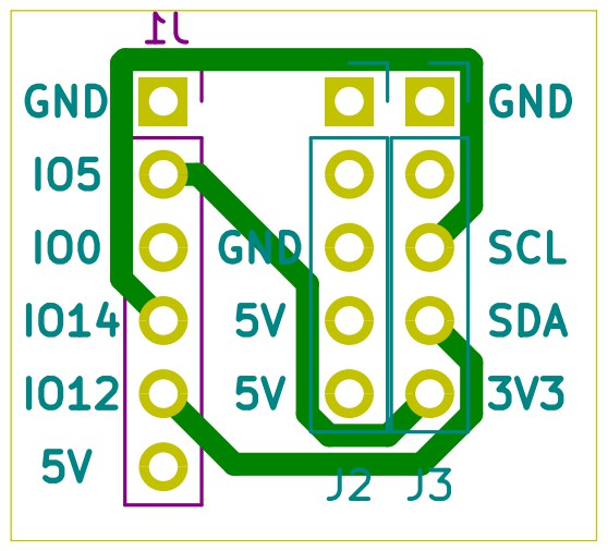
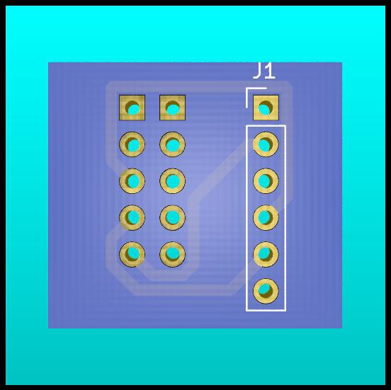
PCB Front Layer:
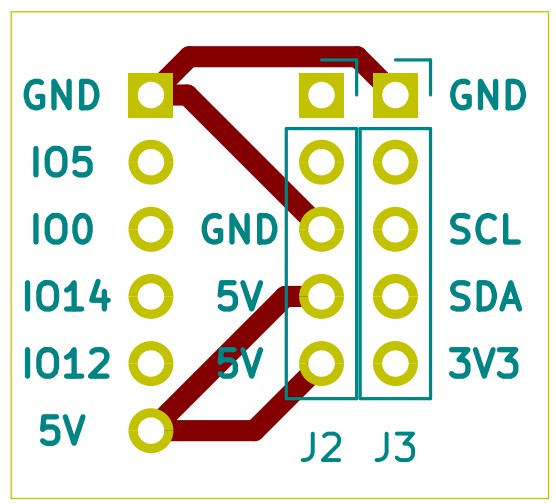
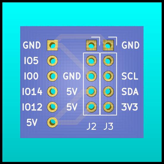
PCB Back Layer:
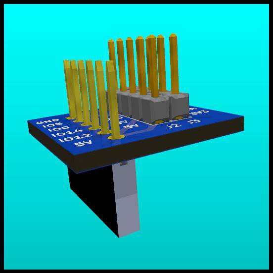
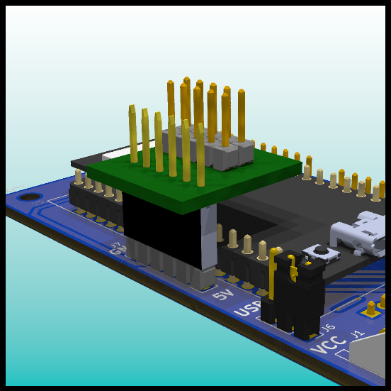
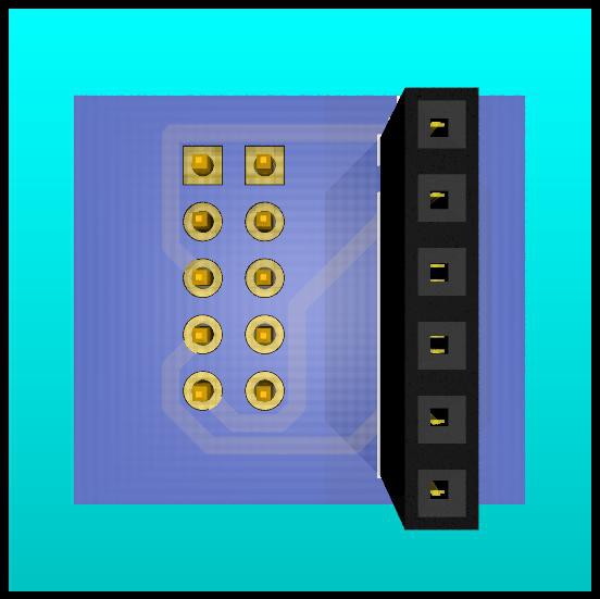
3D Model


Note: The labels in the connector in Buoy B V1.0 (J7 Conn_Extras) are slightly different than the one presented in the original schematic. That schematic has a mistake in the label names for this connector. This information will be explained in future logs.
Discussions
Become a Hackaday.io Member
Create an account to leave a comment. Already have an account? Log In.