 Leonardo Ward
The following diagrams present the physical connections of the different boards and components of the Buoy B V1.0.
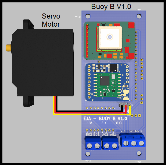
Motors
The board was designed to handle 3 different types of motors, those are:
- Servo Motor
- DC Motor (using the driver TB6612FNG)

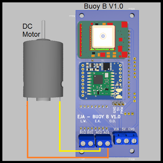
- Stepper Motor (using the driver TB6612FNG)

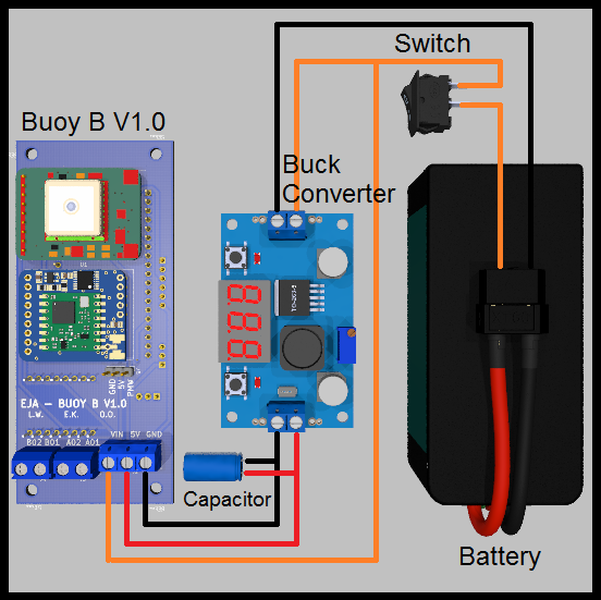
Battery Management
The original design of the board considered the following components:
- Battery (5V < Voltage < 15V)
- PCB Board Buoy B V1.0
- Buck Converter
- Switch
- Extra capacitor
Also, there is an alternative for the battery management, is possible to provide the required voltages with a boost converter and a 3.7V Battery, like the following example:
- 3.7V 1 Cell Battery
- PCB Board Buoy B V1.0
- Boost Converter
- Micro USB Breakout Board
- Switch
- Extra capacitor
- JST-XH 2 Pos female connector and a JST-XH 2 Pos male connector
- 5V Charger (only used to charge the battery)
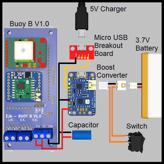
This alternative is valid and possible, but is not ideal for longer working time (compared to the first one). It is important to consider the efficiency of the boost converter. The selected boost converter will have a voltage drop at a current higher than 500mA, that should be taken into consideration.
Discussions
Become a Hackaday.io Member
Create an account to leave a comment. Already have an account? Log In.