 Leonardo Ward
We are happy to announce that we are working on newer versions for our designs!
In previous posts we presented the complete Bill Of Materials and the Schematic for the Buoy B v1.0, to create a better representation of the changes that we are going to make and how they align to our goals we created a Hardware Block Diagram for the Buoy B v1.0. The different colors are used to group different elements on the design, and facilitate the comparison between different diagrams.
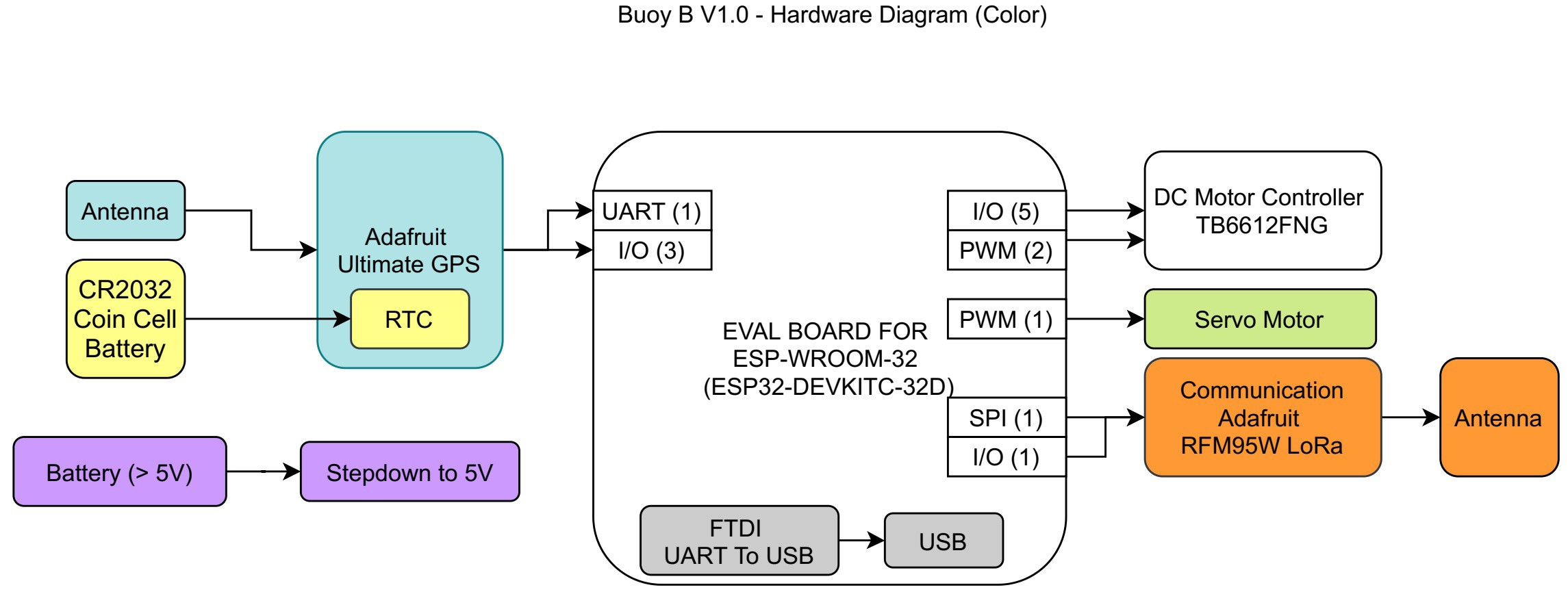
Design components:
- Microcontroller (ESP32)
- GPS with RTC
- LoRa Radio
- Power Supply (Battery + DC-DC Buck Converter)
- Servo Motor
- DC Motor Driver
The previous design incorporates different self-contained development boards to reduce the development time.
For the new version of the device we have the goal to reduce the price as much as possible, to achieve that goal we decided to replace the development boards with the main component in them and create the adapting circuit in our PCB. Usually a change like the one mentioned reduces the overall price, but not always, it is always important to have the reference price of the development board.
The following image contains the Hardware Diagram for the new Buoy B v2.0, it contains mostly the same basic elements (and therefore features), but there are a few additions like the battery charger and a circuit to measure the battery level.
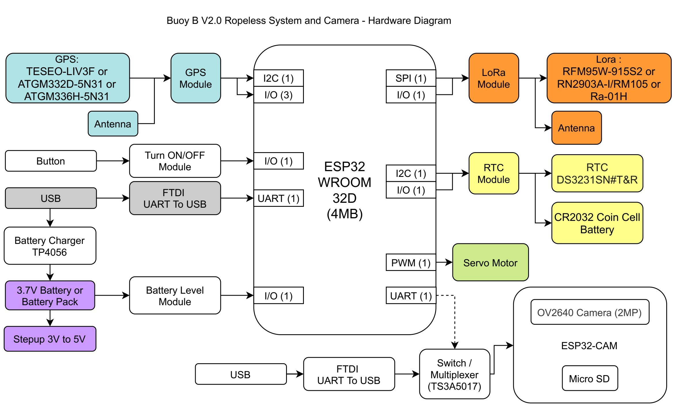
The hardware diagram also includes some ideas that we have for future improvements. The ESP32-CAM can add additional features to our ropeless device, like a camera and data logging capabilities. Even though it is not a priority right now, we will have it as an idea to explore in the future after we meet our main goals.
Discussions
Become a Hackaday.io Member
Create an account to leave a comment. Already have an account? Log In.