 Leonardo Ward
Based on the LoRa development board used for the designs Buoy A v1.0, Buoy B v1.0, Onboard Gateway v1.0, we chose the RFM95W-915S2 to implement in the new prototypes.
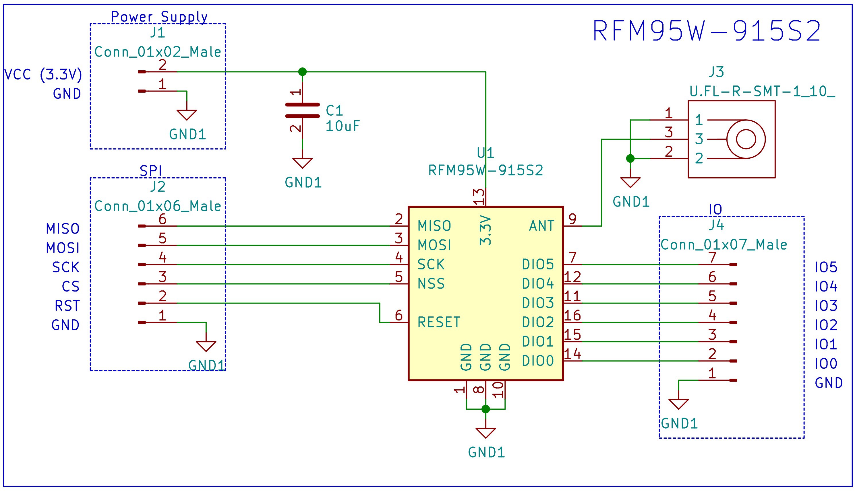
This post presents the design of our own development board used to test the RFM95W-915S2 before it is included in the final design. The schematic is very simple, it includes a decoupling capacitor, a U.FL connector for an external antenna and a few headers.
The design can be found in the following Github repository.
Schematic
Bill of Materials
| Reference | Quantity |
| RFM95W-915S2 LoRa™ Transceiver Module 915MHz SMD | 1 |
| 10 µF ±10% 6.3V Ceramic Capacitor 0805 | 1 |
| U.FL (UMCC) Connector Receptacle, Male Pin 50 Ohm SMD | 1 |
| Conn Header 40POS 2.54 | 1 |
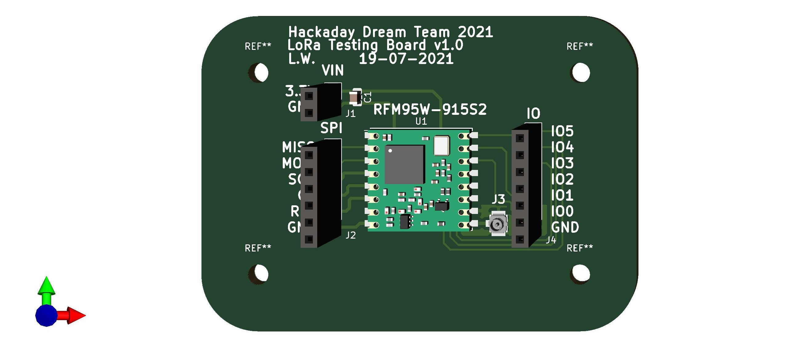
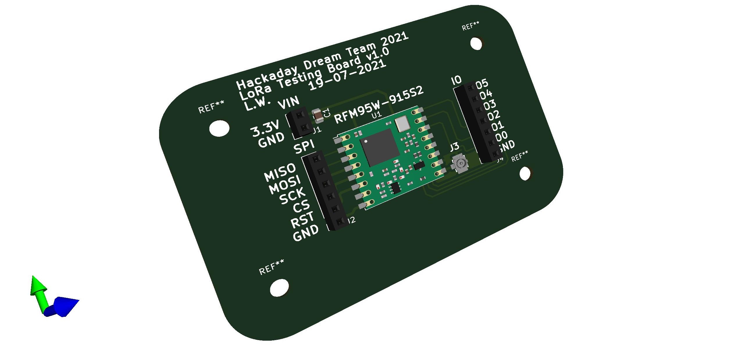
PCB
Discussions
Become a Hackaday.io Member
Create an account to leave a comment. Already have an account? Log In.