 Sam Griffen
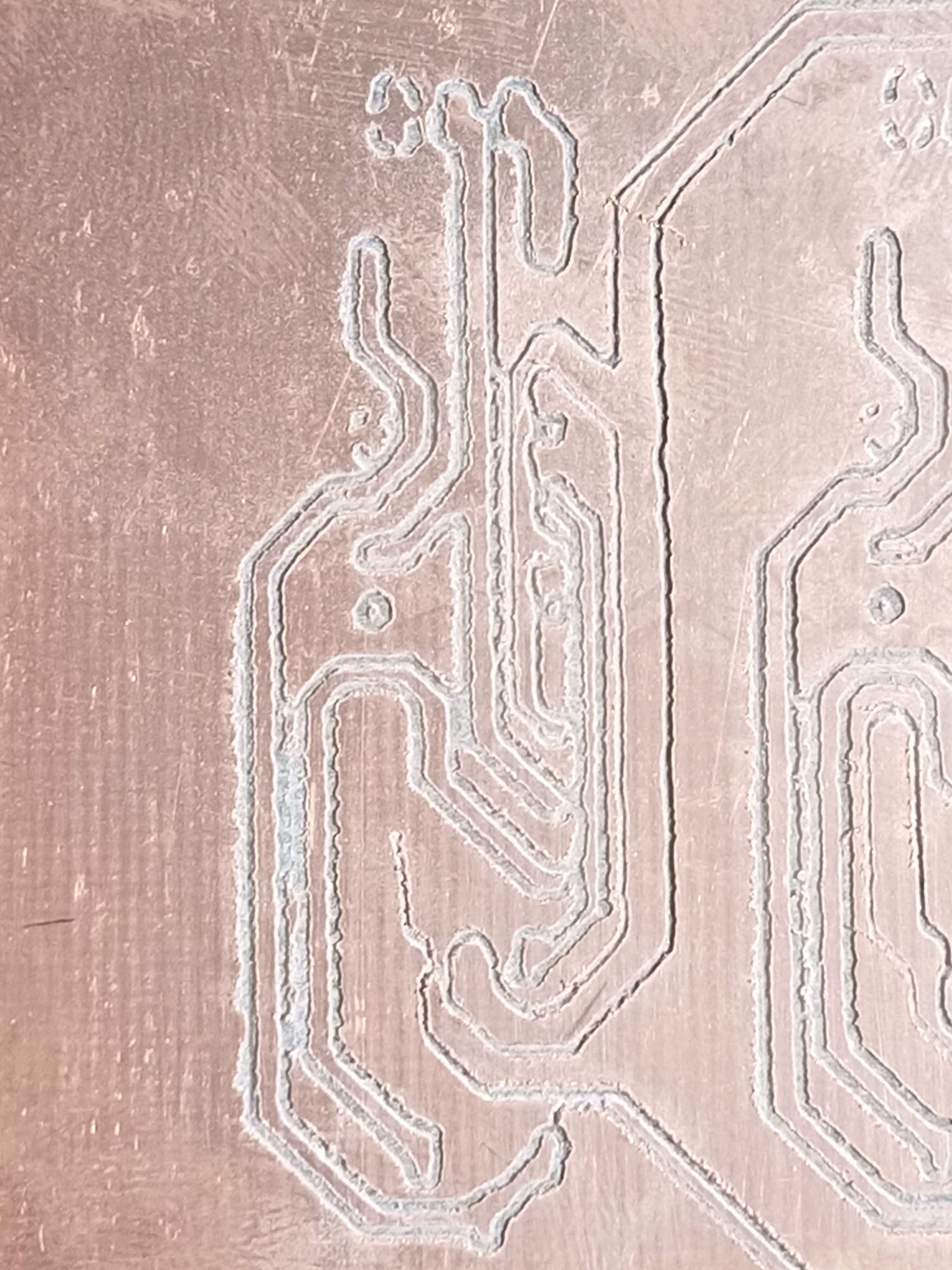
The original build never gave incredibly good results, with the bit either not cutting into the copper, or pushing too far through and ripping the board up, not creating viable traces. When it did break the surface, there was a lot of vibration in the tool, causing inconsistent lines. This is shown in the image below:
After some prodding, it seemed that there was a lot of play in the Z axis, due to the shaft coupler having a spring, rather than being completely solid. I had used a coupler like this one:
 The culprit of Chad's inability to make nice boards?? I have a couple of solid aluminium couplers in the mail to replace the Z axis coupler, however in the meantime I have printed a placeholder coupler in PETG, and fitted that to the axis. No longer is there play in the tool, it is mounted very rigidly, and the results are very clean:
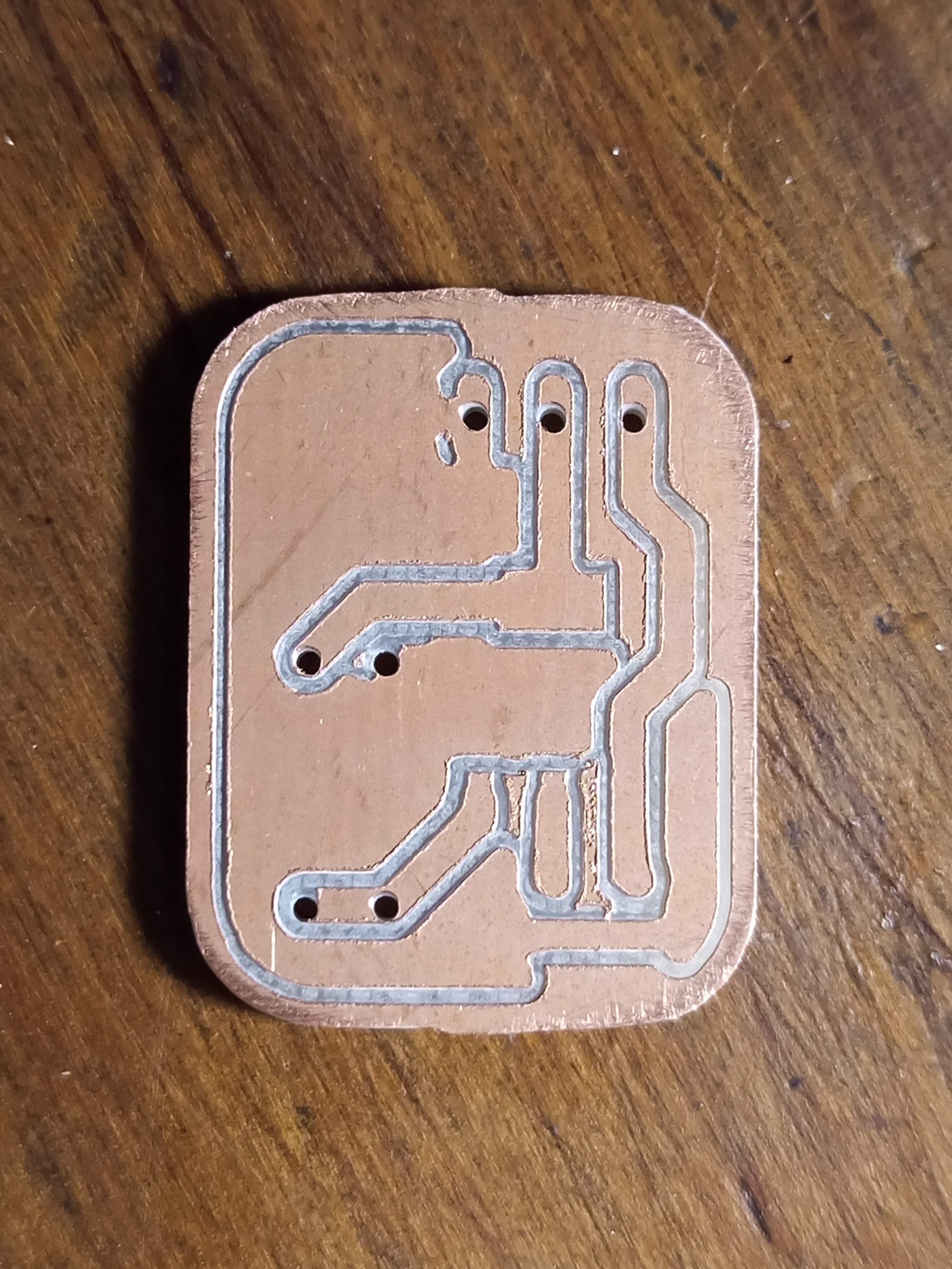
The resulting board is significantly cleaner, and would actually be functional. I'm excited to mill further circuits, I will update once I have a larger board milled.
Discussions
Become a Hackaday.io Member
Create an account to leave a comment. Already have an account? Log In.