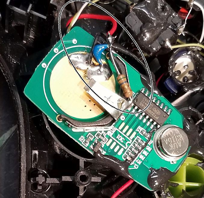
I found two controllers that did not properly trigger the receiver. I saw a similar problem with a non-rechargeable controller I built earlier (see photo). The keyfob board is designed to work with coin cells. When you use a separate power source it lacks a low impedance RF pathway across the battery terminals. To solve this, I added a 1.0 uF ceramic capacitor across the keyfob battery terminals. The picture shows a capacitor with a 5.6 ohm resistor. You don't need the resistor. (The resistor was needed in that earlier design because I ran it on 6 volts, which was too high.) The capacitor solves the problem in the new controller. Some controllers will operate without the capacitor, but why take chances? The instructions have been updated to include the capacitor.

 Andrew Mitz
Discussions
Become a Hackaday.io Member
Create an account to leave a comment. Already have an account? Log In.