 Michael Gardi
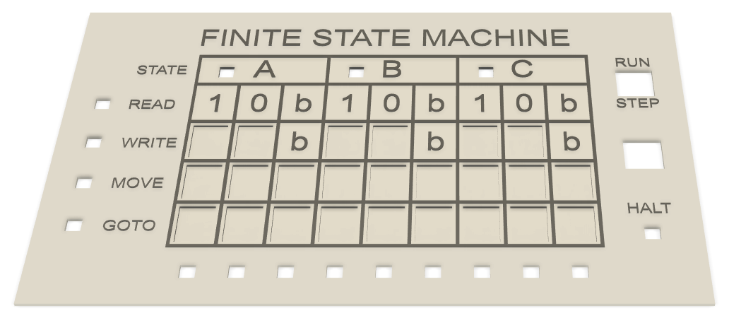
The Finite State Machine Panel will hold the transition table input area. In addition:
- numerous lamps will highlight the current "state" of the machine.
- a slider switch will be added to allow the user to toggle between "Run" and "Step" modes.
- there will be a "Play" button to start or step the machine.
- a special lamp will indicate when the machine has entered the HALT state.
It looks like this:
As with the Tape Panel the controls have been designed specifically for this project.
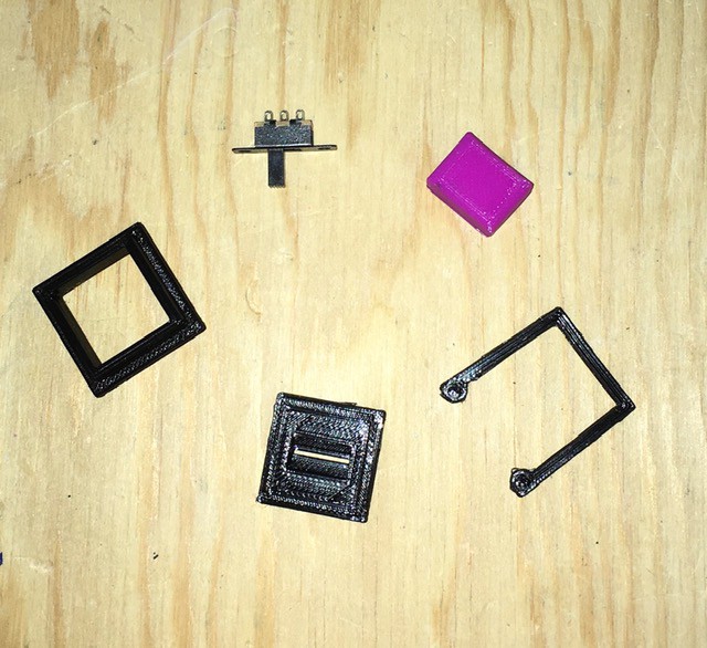
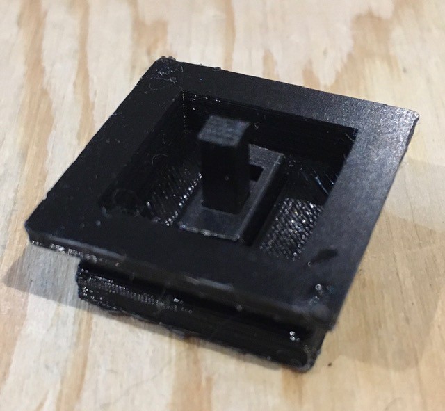
Slider Switch
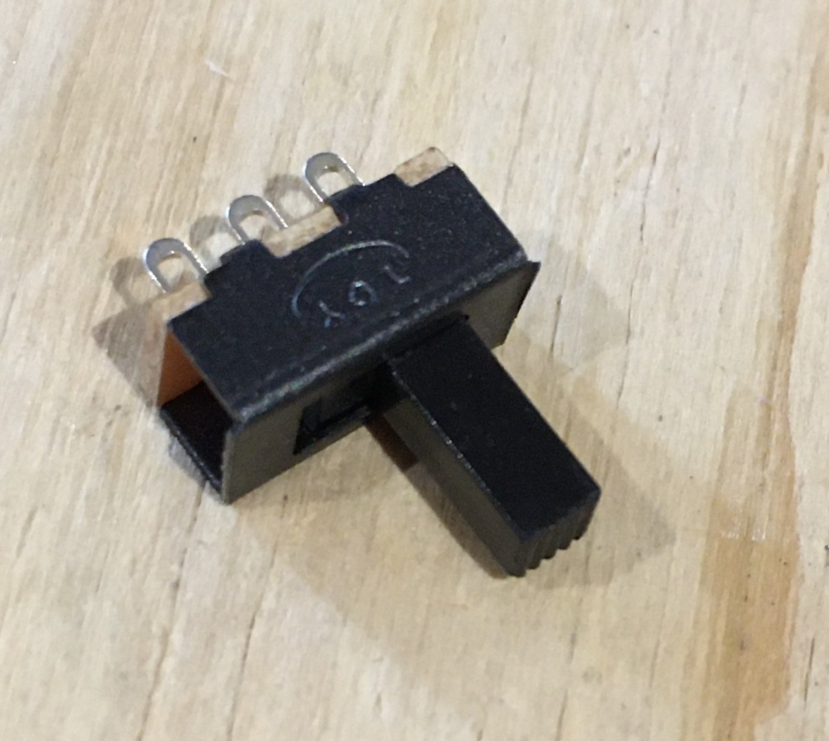
A slider switch will drop into the top right corner of the panel with labels RUN and STEP. It is simply a standard miniature slider switch (Amazon: uxcell® uxcell20Pcs 2 Position 3P SPDT Panel Mount Micro Slide Switch Latching Toggle Switch) with a custom 3D shell to give it a "look" consistent with the rest of the project. Here are the parts:
Start the assembly by cutting off the two top plate mounting holes from the switch then sliding the switch into the base piece as far as it will go. You might need a bit of glue to hold it in place.
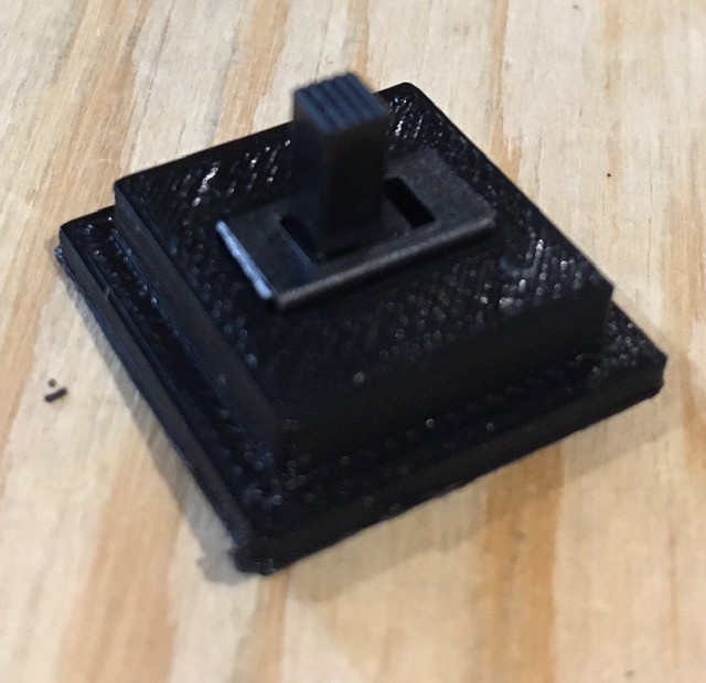
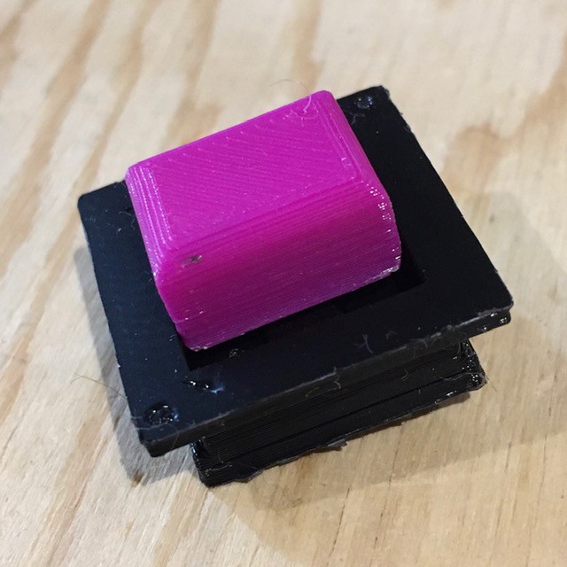
Next attach the base piece to the bottom of the console mounting piece. I used a small amount of glue to hold it firmly in place.
Finally attach the slider to the shaft of the switch. Again apply a drop of glue to hold it in place.
Don't forget to save the C clamp (pictured in the first photo) to hold this switch in place when mounted onto the panel.
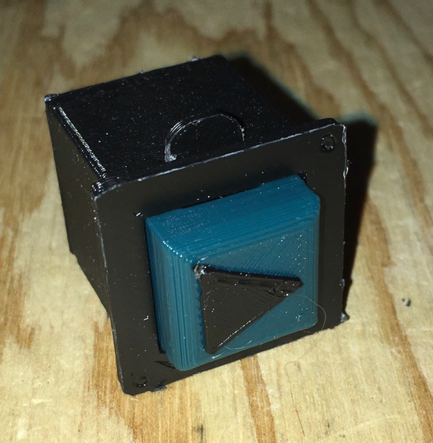
Play Button
Exactly the same is the buttons used for the Tape Panel but with a slightly different look.
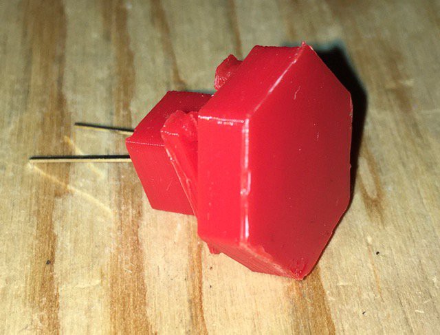
Halt Lamp
Same design as the indicator lamps on the Tape Panel but with a different diffuser design.
Next Steps
When the transition table reader board PCB arrives and I've had a chance to verify the alignment of the hall effect sensors with the input areas, I'll start printing the Finite State Machine board.
Discussions
Become a Hackaday.io Member
Create an account to leave a comment. Already have an account? Log In.