 Michael Gardi
As with the Tape Panel I started by wiring all of the ground leads together for the LEDs and buttons then added a jumper so I could attach the ground(s) to one of the Expander's extra GND pins.
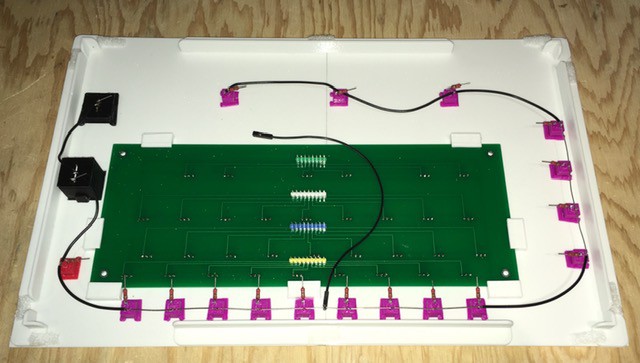
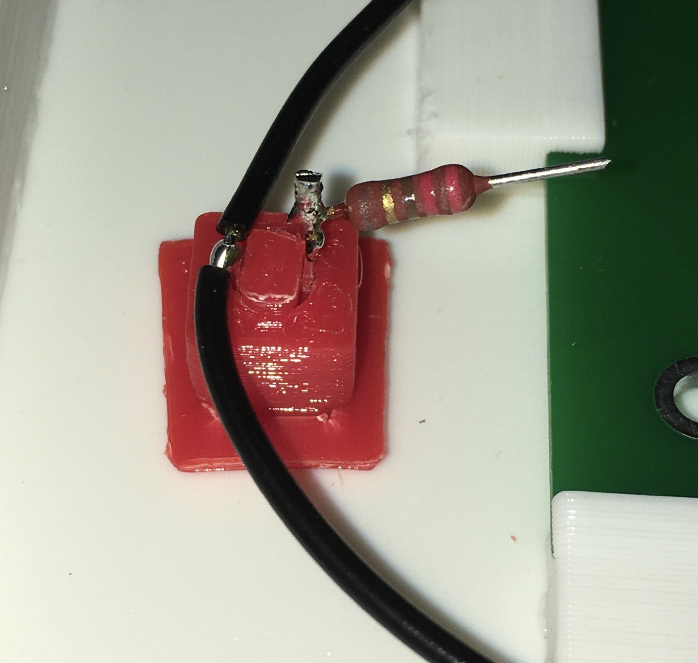
I added limiting resistors to all of the lamps.
Then I mounted a second Expander PCB to the back of the Finite State Machine Panel with two sided tape and connected all 16 of the purple status lamps to it. I had to change the I2C address for this board so it would not conflict with the first. There are jumpers for this.
Here are all the connections made:
| From | To |
|---|---|
| Lamps: C, B, A, READ, WRITE, MOVE, GOTO, A1, A0, Ab, B1, B0, Bb, C1, C0, Cb | Extender Pins: PB7, PB6, PB5, PB4, PB3, PB2, PB1, PB0, PA0, PA1, PA2, PA3, PA4, PA5, PA6, PA7 |
| Transition Table Reader +5V | Extender Pins: VCC |
| Transition Table Reader GND | Extender Pin: GND |
| Wire Ground | Extender Pin: GND |
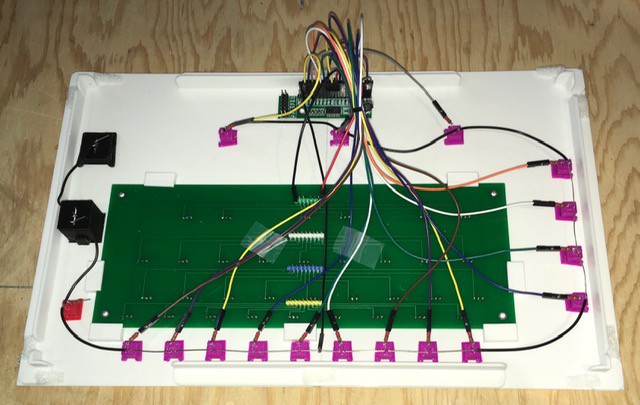
I installed the Finite State Machine Panel onto the console and proceeded to wire the 33 Hall Effect Sensors to the Arduino.
Here are the Arduino pins the sensors are connected to:
| A1 | A0 | Ab | B1 | B0 | Bb | C1 | C0 | Cb | |
|---|---|---|---|---|---|---|---|---|---|
| WRITE | 22 | 23 | n/a | 24 | 25 | n/a | 26 | 27 | n/a |
| MOVE | 28 | 29 | 30 | 31 | 32 | 33 | 34 | 35 | 36 |
| GOTO 1 | 37 | 38 | 39 | 40 | 41 | 42 | 43 | 44 | 45 |
| GOTO 2 | 46 | 47 | 48 | 49 | 50 | 51 | 52 | 53 | 10 |
In addition the following connections were made:
| From | To |
|---|---|
| HALT Lamp | Arduino Pin: 11 |
| PLAY Button | Arduino Pin: 12 |
| RUN/STEP Switch | Arduino Pin: 13 |
| Extender Pin: GND | Arduino Pin: GND |
| Extender Pin: VCC | Arduino Pin: VCC |
| Extender Pin: SCL | Tape's Extender Pin: SCL |
| Extender Pin: SDA | Tape's Extender Pin: SDA |
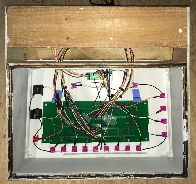
Done Wiring
That's it. The Turing Machine Demonstrator hardware is completed. More testing and a lot of coding are in my immediate future.
Discussions
Become a Hackaday.io Member
Create an account to leave a comment. Already have an account? Log In.