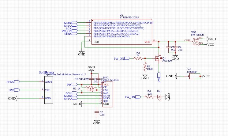
I'm adding schematics with a bit of explanation

Now to details.
Attiny85 5 pin configuration
Normally to connect NRF24L01 module you need 5 pins, 3 SPI + 2 control pins (CE,CSN). In that case module will work in it's perfect conditions, power consumption would be on minimum (since chip will be idling most of the time) and i have no more pins to use.
Attiny85 4 pin configuration
However plan is to connect external sensor, therefore i need to free up some space. Step one - CE pin will be tied to Vcc, and Vcc will be switched on and off when i need it via mosfet. This way i win no extra pins, but i have ability to switch on and of power to the soil moisture sensor and radio module at the same time using single pin.
Attiny85 3 pin configuration
Using this article and this library it is possible to win one more pin using multiplexing (in other words using single pin to simulate two, CSN and SPI_CLK in our case. However this setup is not that trivial to start and before going this way i'll need to start with 5 pin config and progress slowly to 3 pin.
Atmel328P receiver node
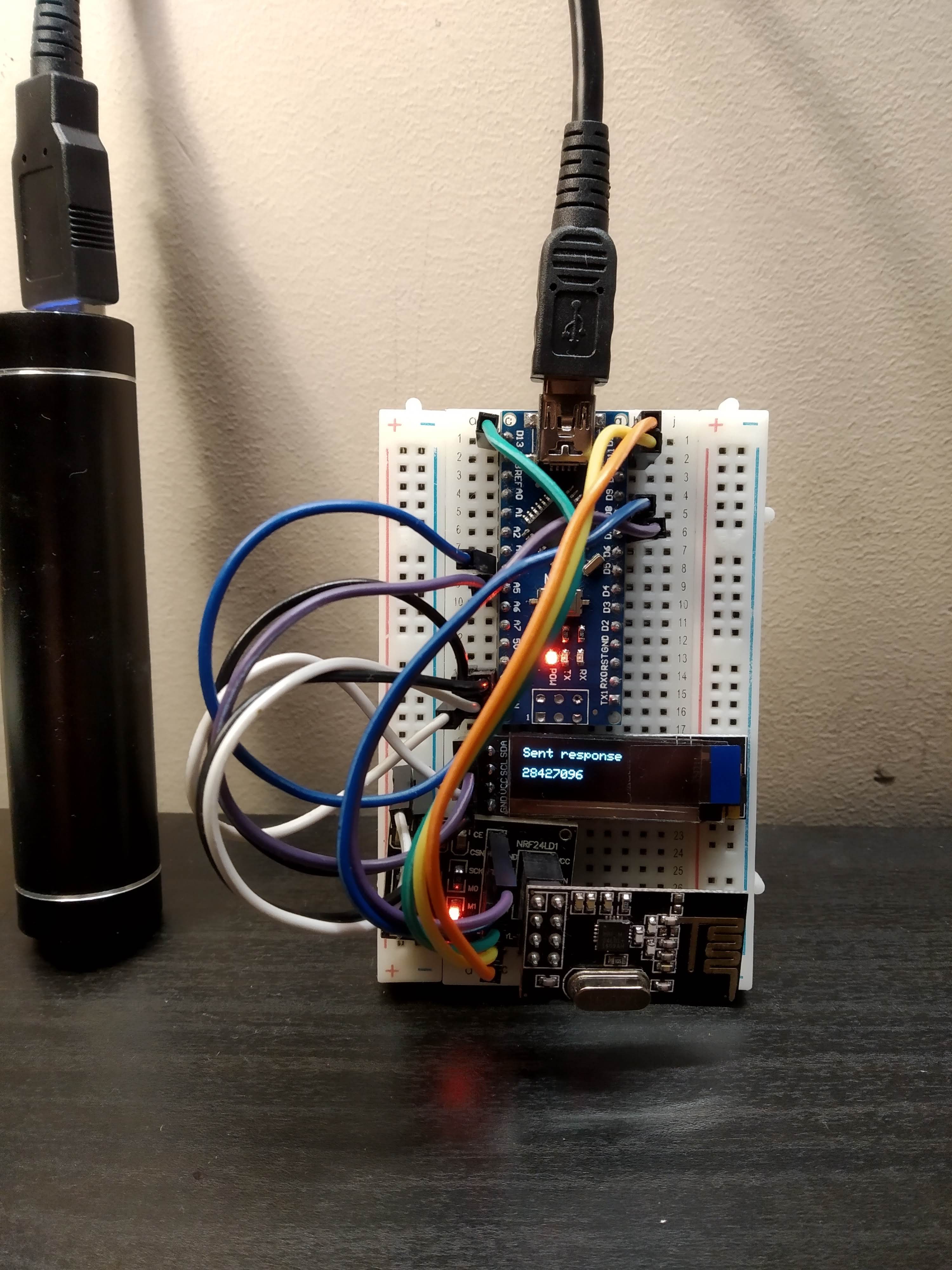
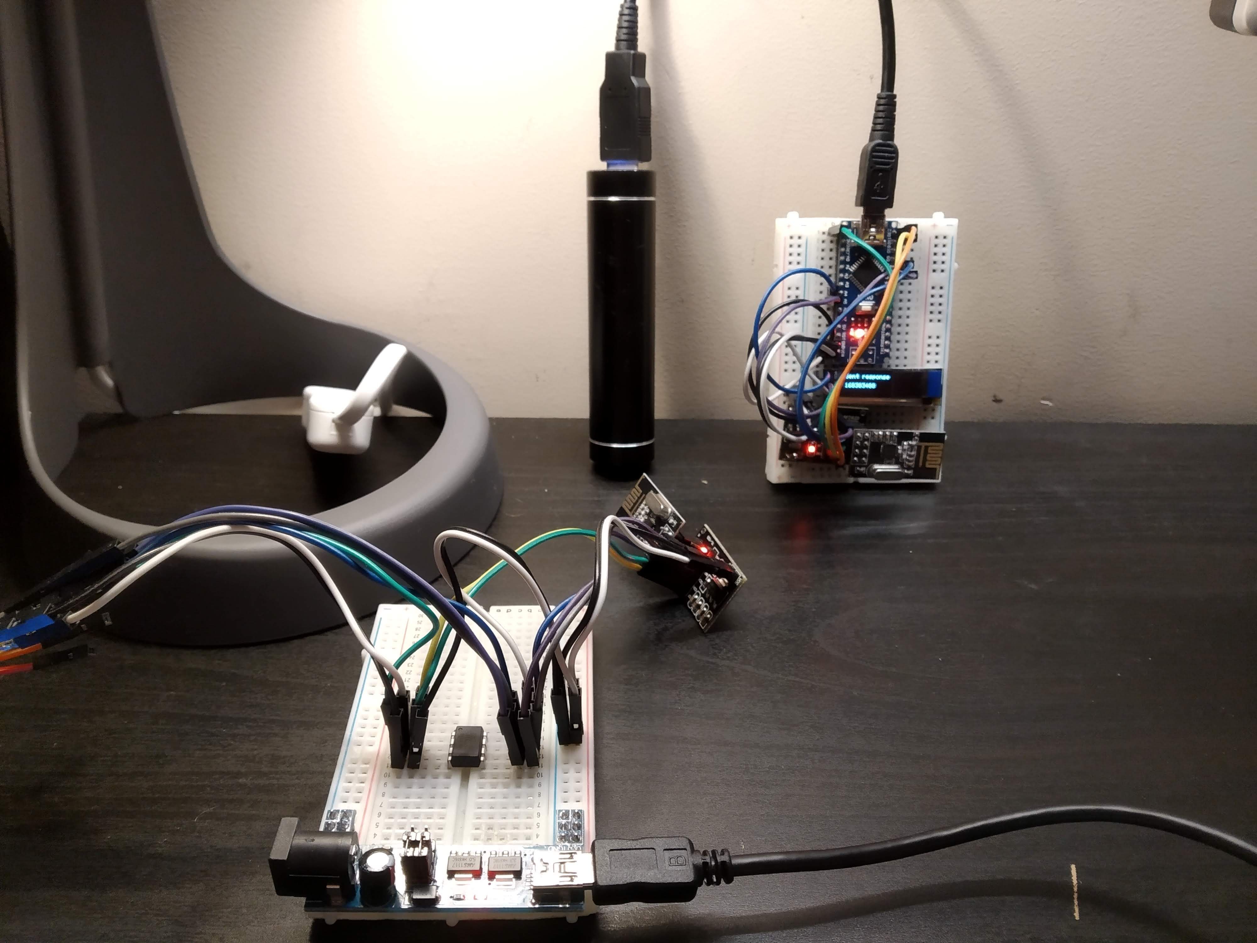
To test any configuration i need to have second node in constant monitoring mode. Here i'm not limited to attiny85 and I'd prefer to have something with Serial and even a oled screen. So here it is:

I slightly modified starter ping-pong example from RF24 library to add OLED printing and now i'm able to listen Attiny85 in 5-pin configuration from another breadboard.

To be continued...
 andriy.malyshenko
Discussions
Become a Hackaday.io Member
Create an account to leave a comment. Already have an account? Log In.