 andriy.malyshenko
With previos step done i'm ready to assebmle final 3-pin setup
Using schematics taken from here, and recommendation from here i replaced resistor with 20K, and cap with 10nF.
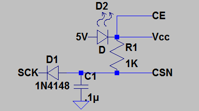
No need to change library, it is already adjusted to work with 3-pin config, only need to initialize it with same pin numbers for CE and CSN, like this
#define NRF_CE    3
#define NRF_CSN   3
RF24 radio(NRF_CE, NRF_CSN);
Actual pin 3 will not be used by library and it is still available for Serial.
Pin 4 is connected to Analog soil moisture sensor and i'm ready to send out actual data.
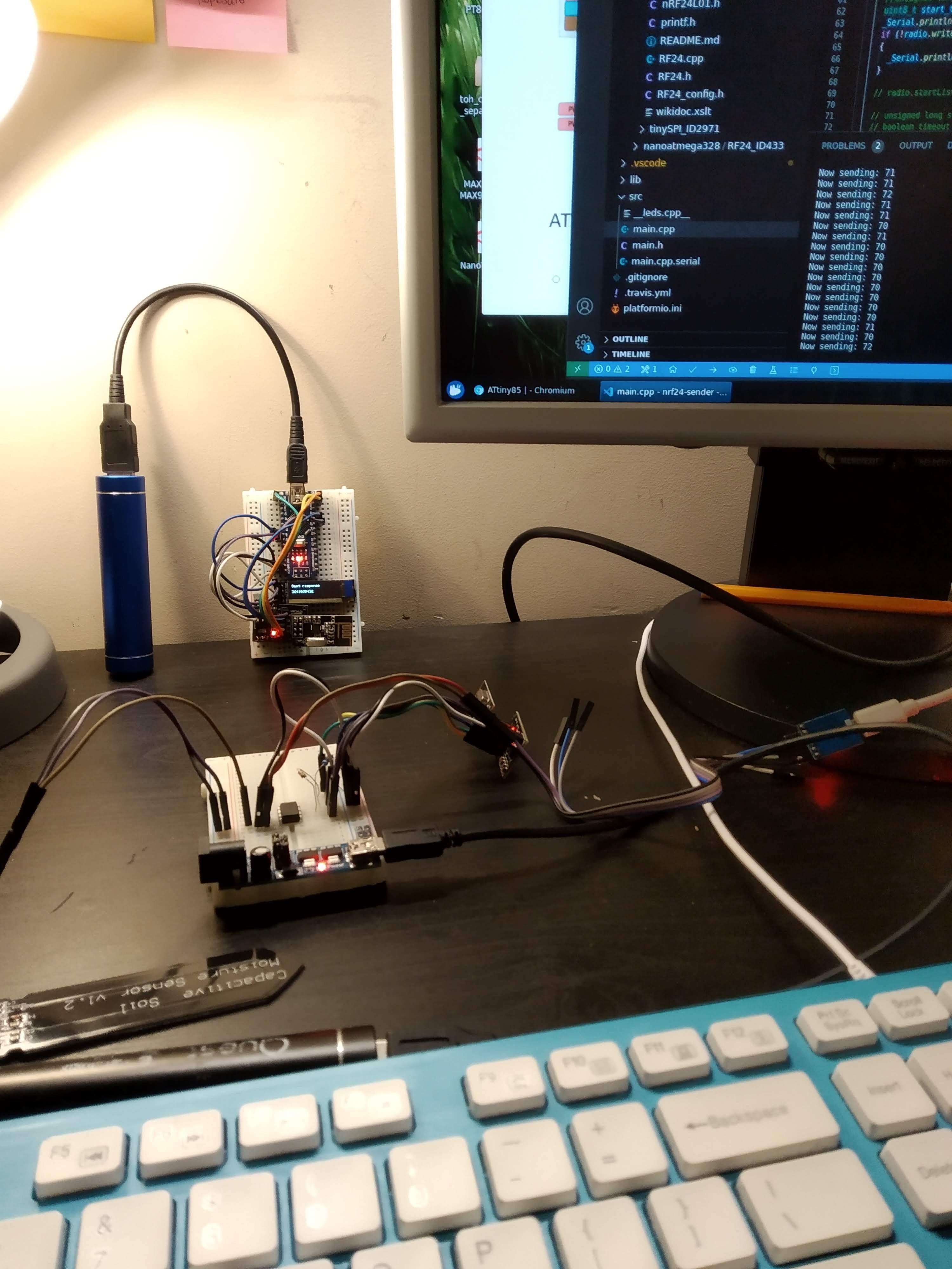
Image is not much different from previous one, but in fact numbers are actual sensor readings.
Next step is to play around with energy saving and sleep modes. I still have couple more weeks before PCBs should arrive.
Discussions
Become a Hackaday.io Member
Create an account to leave a comment. Already have an account? Log In.