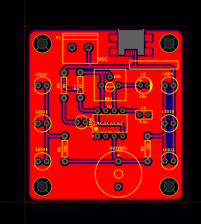
It is an acoustooptic alarm circuit project, easily get.
Open source: GPL 3.0
Step 1: Circuit Simulation and Principle Description
This circuit is relatively simple, so the core is a multivibrator composed of NE555.
Because the multivibrator is really unstable, it's in a state of transient stability, where one goes up and one goes down, and then the two rows of leds light up across each other.
C2, R1, R4 and NE555 together constitute a multivibrator circuit. When just powered on, pin 2 and pin 6 of NE555 are in low level state, pin 3 outputs high level, LED1~3 is not on, AND LED5~7 is lit. The power supply keeps charging the C2 capacitor. When the voltage reaches 2/3 of the power supply, the 3-pin output becomes low level. The discharge tube inside the 555 chip is switched on. The circuit continues this process by changing the resistance of the R4 potentiometer to change the frequency at which the buzzer sounds and the speed at which the LED flashes.
Step 2: Notes
(1) During the simulation, please pay attention to switch to the simulation mode, and the device should be called in the simulation library;
(2) Pay attention to the welding of pole devices in the welding process to avoid damaging the devices and affecting the circuit function;
(3) If the output waveform is to be tested, disconnect R8, R9 and the buzzer.
Step 3: Extensive Application
Can add a temperature sensor circuit on this basis, when the temperature reaches how many degrees Celsius alarm;
Or add personal pyroelectric sensor, when someone comes by the alarm, sleep at night must prevent thieves; Also can design a small timing circuit in front, when a small alarm clock function.
Step 4: Files
Enclosed the pictures of the files for reference.


