 zpekic
Classic CPUs execute instructions by going through a predetermined set of machine states. With SIFP16's unique design, these machine states are at the same time proper CPU instructions. This means, that regardless of the program, SIFP-16 always only executes 14 CPU instructions and goes over 14 possible states.
In absence of special execution conditions (HOLD, TRACE, INTERRUPT), only 2 instructions / states are executed:
- FETCH:
- CPU executes following instruction: r_p_M_IMM & r_a_NOA & r_x_NOX & r_y_NOY & r_s_NOS (this will generate VMA and RnW both high)
- FETCH signal is asserted on the bus (useful for debugging)
- Data bus input is loaded into 16-bit reg_i (instruction register)
- EXECUTE:
- CPU executes whatever is in reg_i
- go back to FETCH
The simplest control unit implementation could simply be a flip-flop, driving a 2->1 MUX, one input hard coded to fetch, other connected to reg_i.
But to make a full-fledge processor, handling additional states makes it a bit more complex:
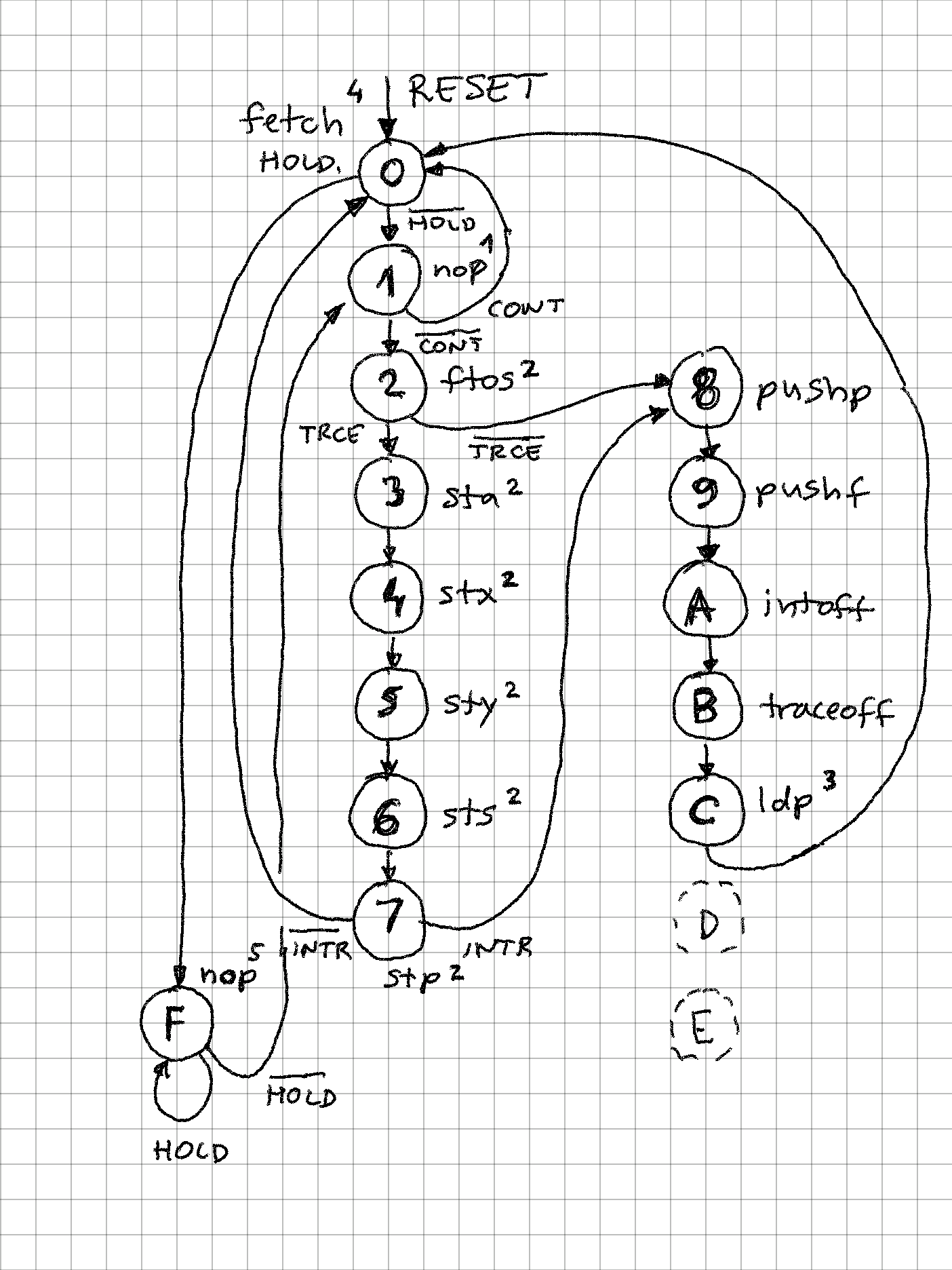
Notes for the diagram above:
1. Machine instruction is "NOP", but instead contents of reg_i is executed, loaded in step 0
2. If TRCE (trace condition) is asserted, all processor registers are output on the data bus, and their index on address bus. This is useful to inspect state of each register after each instruction
3. LDP loads P (program counter) from data bus, but instead of VMA (valid memory address), INTA (interrupt acknowledge) signal is asserted to indicate that an interrupt vector should be presented to the data bus.
4. FETCH cycle is started after RESET, and all other states eventually lead here
5. State / instruction 15 is a "dead loop" as long as external circuit holds HOLD high. During that time HOLDA output is high and bus is tri-state ("Z" in VHDL)
Following control signals determine the flow:
- HOLD - serviced after each fetch, before execution starts
- CONT - no interrupts or tracing, allows for fast fetch -> execute -> fetch ... sequence
- INTR - interrupt enable flag is true, and external interrupt signal went from low to high (edge triggered)
- TRCE - trace mode - external trace pin, or internal flag is set, causing all registers to be output after each instruction
[0003]CLC:  r_a = STA, r_s = M[PUSH];
MW,FFFD DEAD
RV,  F= 0010
RV,  A= DEAD
RV,  X= BEEF
RV,  Y= BEEF
RV,  S= FFFD
RV,  P= 0073
[0004]  r_p = M[IMM], r_a = LDA;
MR,0074 0000
RV,  F= 0018
RV,  A= 0000
RV,  X= BEEF
RV,  Y= BEEF
RV,  S= FFFD
RV,  P= 0075
[0006]ACSet:  SLC;
RV,  F= 0018
RV,  A= 0000
RV,  X= BEEF
RV,  Y= BEEF
RV,  S= FFFD
RV,  P= 0076
[0007]  r_a = LDA, r_s = M[POP];
MR,FFFD DEAD
RV,  F= 0000
RV,  A= DEAD
RV,  X= BEEF
RV,  Y= BEEF
RV,  S= FFFE
RV,  P= 0077
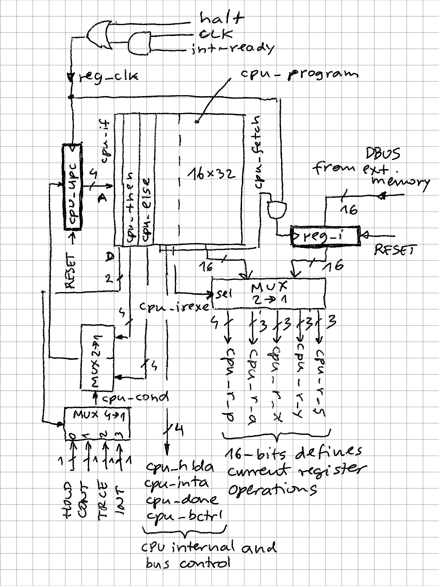
The actual implementation of control unit is centered around a ROM of 16 instructions (2 are not used). The instruction width is 32 bits:
- 2 bits to select the internal condition ("if") - note that 5 conditions are possible, if "then" and "else" are same, this becomes "true"
- 4 bits to determine next instruction if condition is true ("then")
- 4 bits to determine next instruction if condition is false ("else")
- 6 control bits
- 16-bit instruction driving the P, A, X, Y, S registers
-- instruction word
signal cpu_instruction: std_logic_vector(31 downto 0);
alias cpu_if:      std_logic_vector(1 downto 0) is cpu_instruction(31 downto 30); -- select condition ("IF")
alias cpu_then:  std_logic_vector(3 downto 0) is cpu_instruction(29 downto 26); -- next state if condition true ("THEN")
alias cpu_else:  std_logic_vector(3 downto 0) is cpu_instruction(25 downto 22); -- next state if condition false ("ELSE")
alias cpu_hlda:  std_logic is cpu_instruction(21); -- 0: bus hold (tri-state) machine cycle
alias cpu_inta:  std_logic is cpu_instruction(20); -- 0: load interrupt vector
alias cpu_done:  std_logic is cpu_instruction(19); -- 1: last machine cycle in instruction
alias cpu_bctrl: std_logic is cpu_instruction(18); -- 0: alternative bus control (ABUS = register address; VMA, PnD, RnW = '0')
alias cpu_irexe: std_logic is cpu_instruction(17); -- 1: execute from instruction register
alias cpu_fetch: std_logic is cpu_instruction(16); -- 1: fetch
-- format of lower 16-bit is exactly the same like the instructions stored in external memory!
alias cpu_i: std_logic_vector(15 downto 0) is cpu_instruction(15 downto 0);
Note:
- There is no "random decode logic" - output of MUX cpu_r_? drives directly 5 programmable registers in the CPU
- CPU instructions are reused to drive CPU control logic (for example LDP allows loading program counter from stack, but is here also reused to load interrupt vector etc.)
- Maximum delay path is very short, just a ROM lookup + 2 gate delays (on my old FPGA board with 50MHz max clock, CPU works are 25MHz, executing at 12.5MIPS)
- cpu_done signal allows measuring throughput (instructions per second) and also help external trace circuit to implement single stepping
- cpu_bctrl signal allows alternative driving of the bus. When low, VMA is low so in TRCE mode register output is not interpreted as memory write.
- Execution times are very predictable:
- 2 clock cycles per instruction (no trace)
- 8 clock cycles when in trace mode
- 8 clock cycles to service interrupt (this includes automatic saving of P and F registers to stack)
-- CPU program
-- CPU always executes only these instructions continously
-- except at step 1 when the instruction executed is coming from instruction register
-- which was loaded from external memory
-- this works because the lower 16 bits of the instructions in this program are same as
-- instruction format stored in external memory
constant cpu_program: mem16x32 := (
    -- basic loop (fetch / execute)
    -- 0: fetch, then hold or execute
    if_hold & X"F" & X"1" & "000101" & c_FETCH,
    -- 1: execute, then continue (fetch next instruction) or special path
    if_cont & X"0" & X"2" & "001110" & c_NOP,

    -- trace routine outputs register index on A bus and value on D bus
    -- 2: output F(flags), if trace then output other regs else push regs (interrupt)
    if_trce & X"3" & X"8" & "000000" & c_FTOS,
    -- 3: output A, continue
    if_intr & X"4" & X"4" & "000000" & r_p_NOP & r_a_A     & r_x_NOX & r_y_NOY & r_s_NOS,
    -- 4: output X, continue
    if_intr & X"5" & X"5" & "000000" & r_p_NOP & r_a_NOA & r_x_X     & r_y_NOY & r_s_NOS,
    -- 5: output Y, continue
    if_intr & X"6" & X"6" & "000000" & r_p_NOP & r_a_NOA & r_x_NOX & r_y_Y      & r_s_NOS,
    -- 6: output S, continue
    if_intr & X"7" & X"7" & "000000" & r_p_NOP & r_a_NOA & r_x_NOX & r_y_NOY & r_s_S,
    -- 7: output P, if interrupt then push regs else fetch (new instruction)
    if_intr & X"8" & X"0" & "001000" & r_p_STP & r_a_NOA & r_x_NOX & r_y_NOY & r_s_NOS,

    -- interrupt routine pushes P and F on the stack, disables tracing and interrupts, and then load the int vector
    -- 8: push P, continue
    if_cont & X"9" & X"9" & "000100" & c_PUSHP,
    -- 9: push F, continue
    if_cont & X"A" & X"A" & "000100" & c_PUSHF,
    -- A: turn trace flag off, continue
    if_cont & X"B" & X"B" & "000100" & c_INTOFF,
    -- B: turn interrupt enable off, continue
    if_cont & X"C" & X"C" & "000100" & c_TRACEOFF,
    -- C: load intrrupt vector, then fetch next instruction
    if_cont & X"0" & X"0" & "010100" & c_LDP,

    -- unused, reserved for future use
    -- D: unreachable nop
    if_cont & X"0" & X"0" & "000100" & c_NOP,
    -- E: unreachable nop
    if_cont & X"0" & X"0" & "000100" & c_NOP,

    -- bus hold routine
    -- F: hold (tri-state) until HOLD signal detected low, otherwise execute
    if_hold & X"F" & X"1" & "100000" & c_NOP
);
Discussions
Become a Hackaday.io Member
Create an account to leave a comment. Already have an account? Log In.