 Andrei Florian
-
1Required Components
![]()
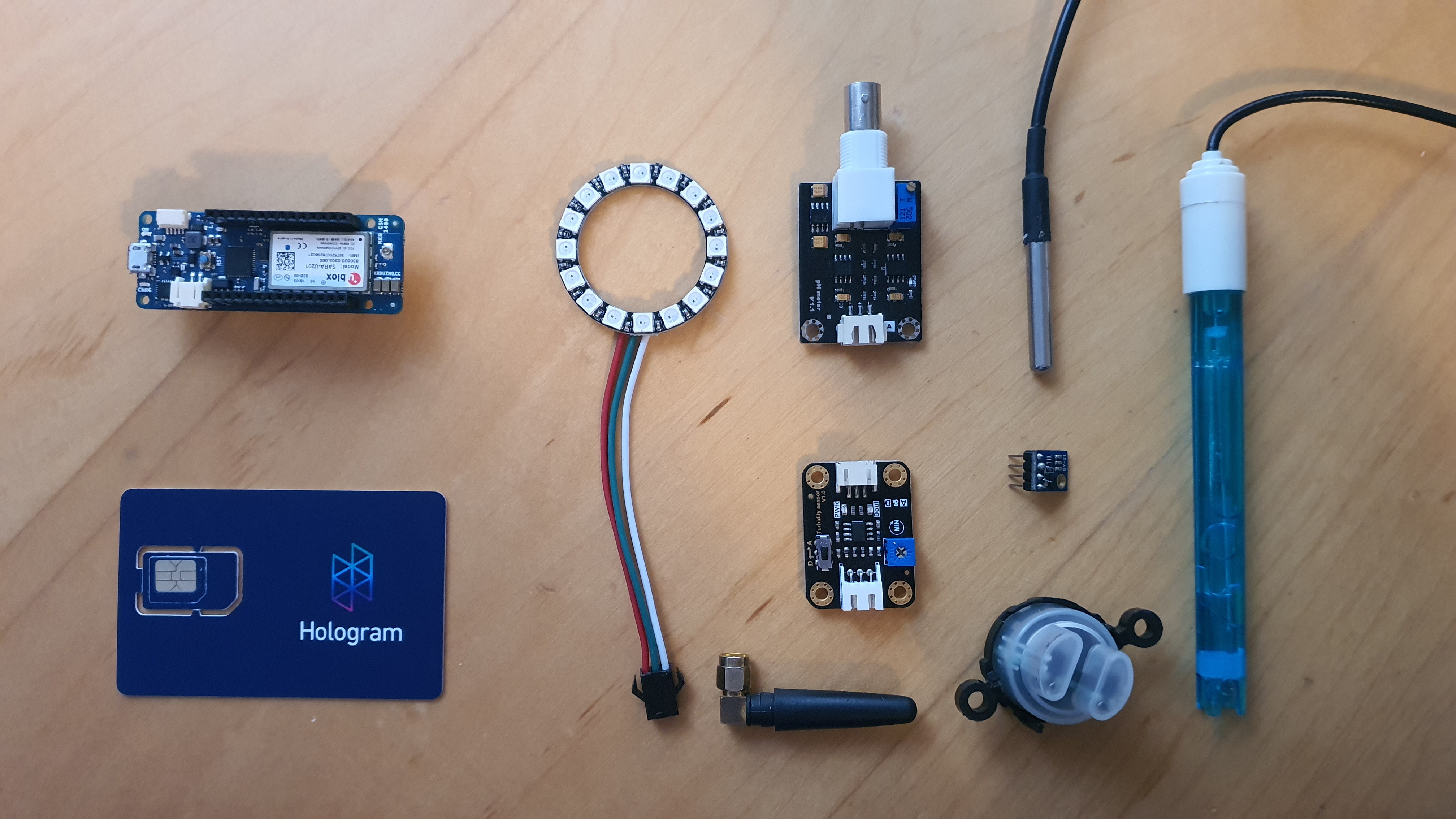
Below is a copy of the BOM for the project. The complete BOM with links and costs in attached above in the article.
- Arduino MKR GSM 1400
- 3.7v 1,800mAh LiPo batter
- GY-21 Temp and Humidity
- Water pH Sensor
- Water turbidity Sensor
- Water temperature Sensor
- Wires, breadboard, button
- Neopixel ring
- Hologram Sim
- Solar panel module
- Plastic for enclosure
-
2Required Machinery
![]()
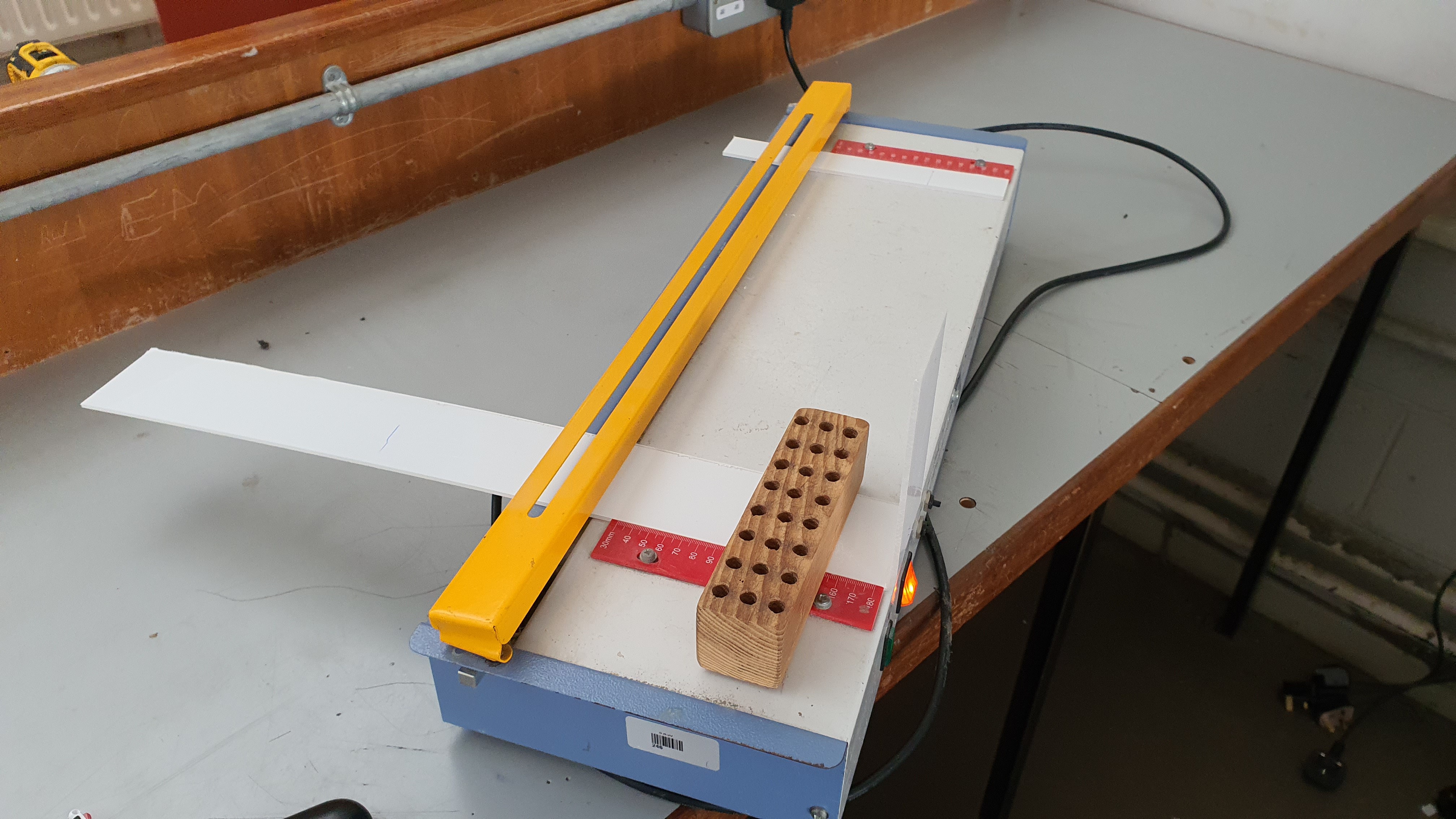
Below is a list of all the machinery needed to hand build the enclosure for the project. Note that CAD files are attached of the enclosure if you prefer 3D printing it.
- Bandsaw
- Hot wire strip heater
- Sander
-
3Connecting the Circuit
![]()
The diagram above shows the circuit of the project. Please follow it to connect all the modules together. Note that if you are not using the solar powered version, the LiPo battery is to be connected to the MKR GSM LiPo battery socket.
![]()
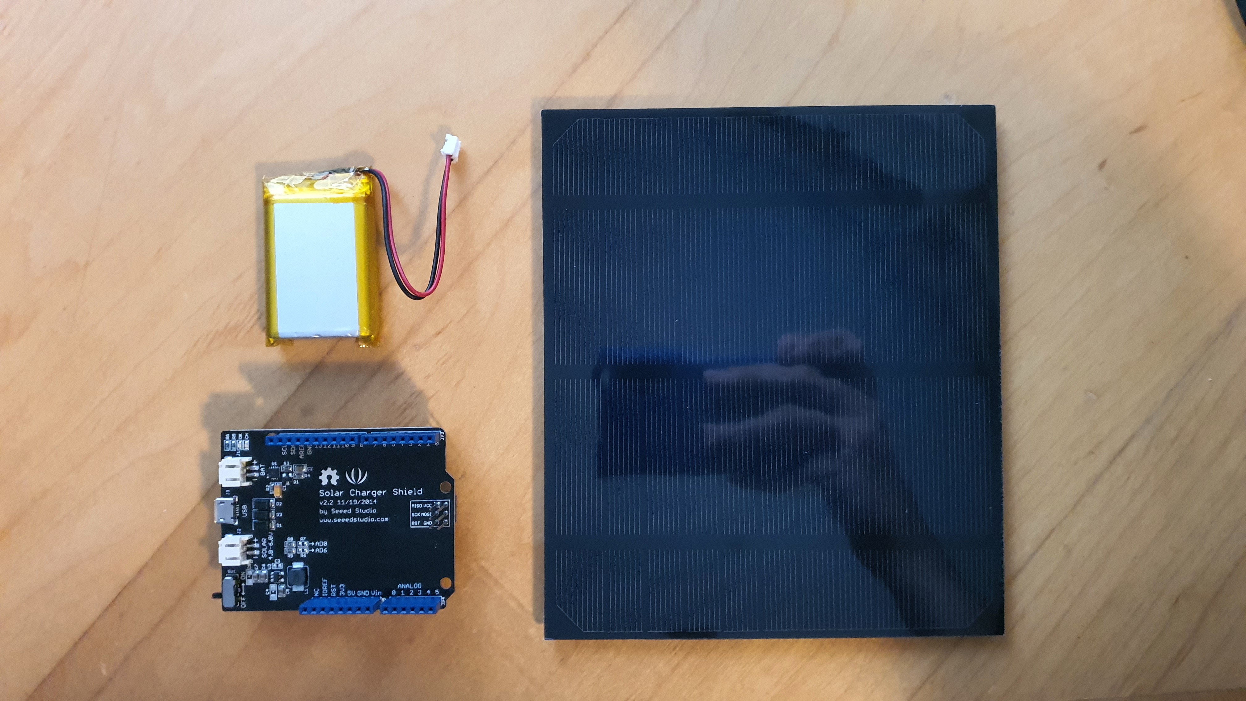
If the solar shield is being used, please connect the solar panel and LiPo battery to corresponding ports on the shield and ensure it is turned on when operating the device. Connect pins as instructed below.
Shield Pin
MKR GSM Pin
5v
VIN
GND
GND
-
4Setting up IoT Central
Now that everything is connected. We need to set up IoT Central. There are a few prerequisites before we can get started.
- Create a Microsoft account if you do not have one
- Create a free Azure account if you do not have one
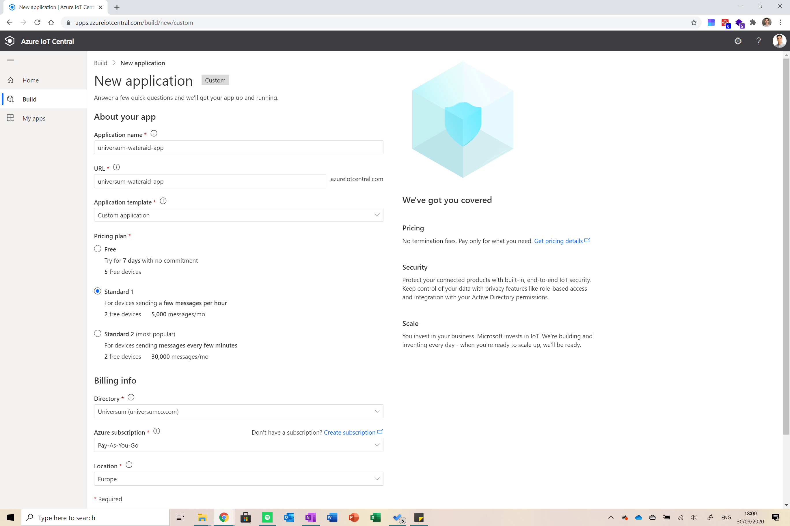
Ok, let’s get going. Go to https://apps.azureiotcentral.com/myapps and click on the plus icon in the top left of the screen to create a new app.
![]()
Fill everything in as shown above and then click on create. You will be redirected to your dashboard. Now click on device templates from the menu on the right of the screen. Click on the new button and then on IoT Device. Follow the steps until you are directed to your template.
![]()
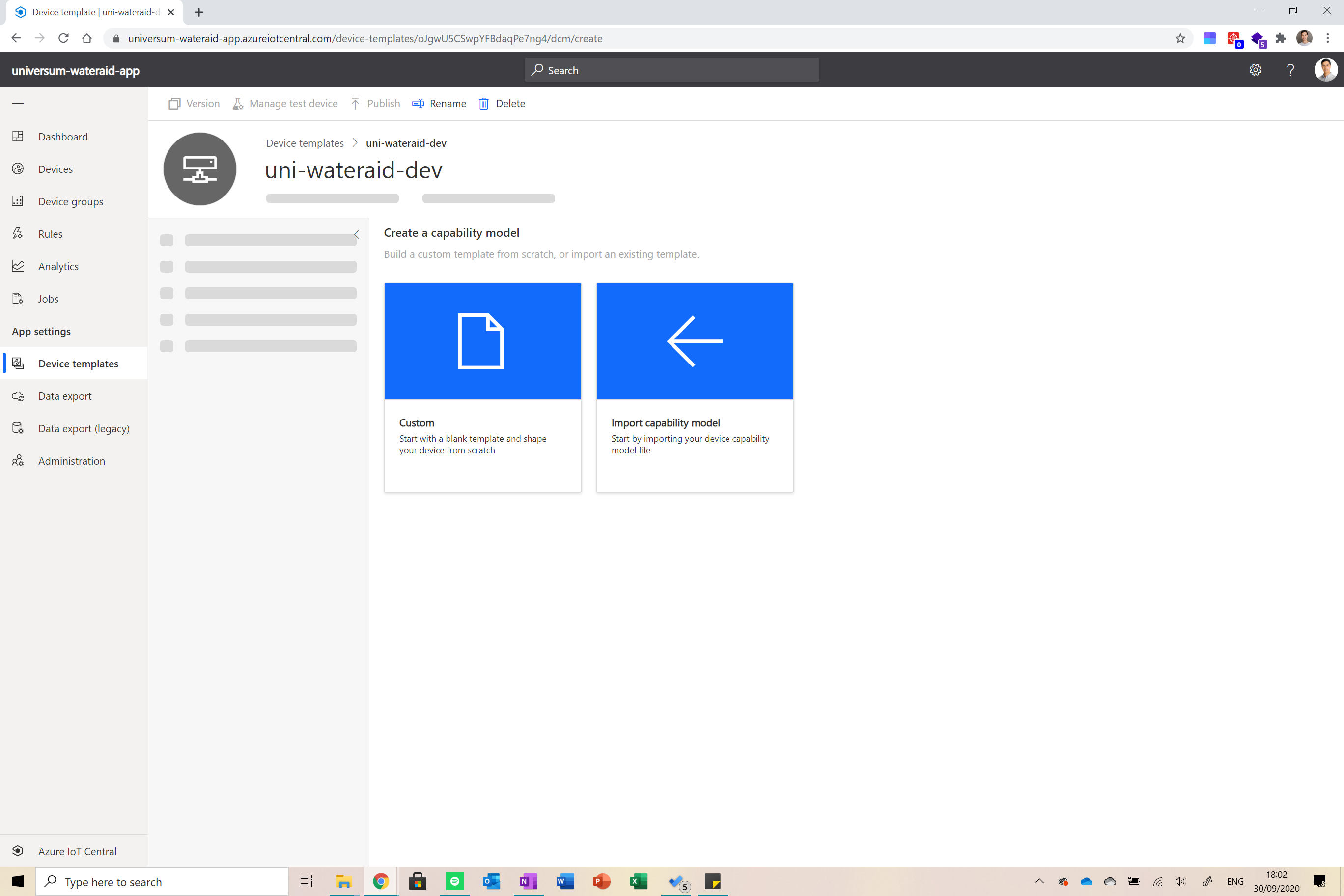
Now, click on Custom to create a capability model. The next thing we want to do is click on Cloud Properties from the left of the screen and add a property for the geolocation of the enterprise device as shown below.
![]()
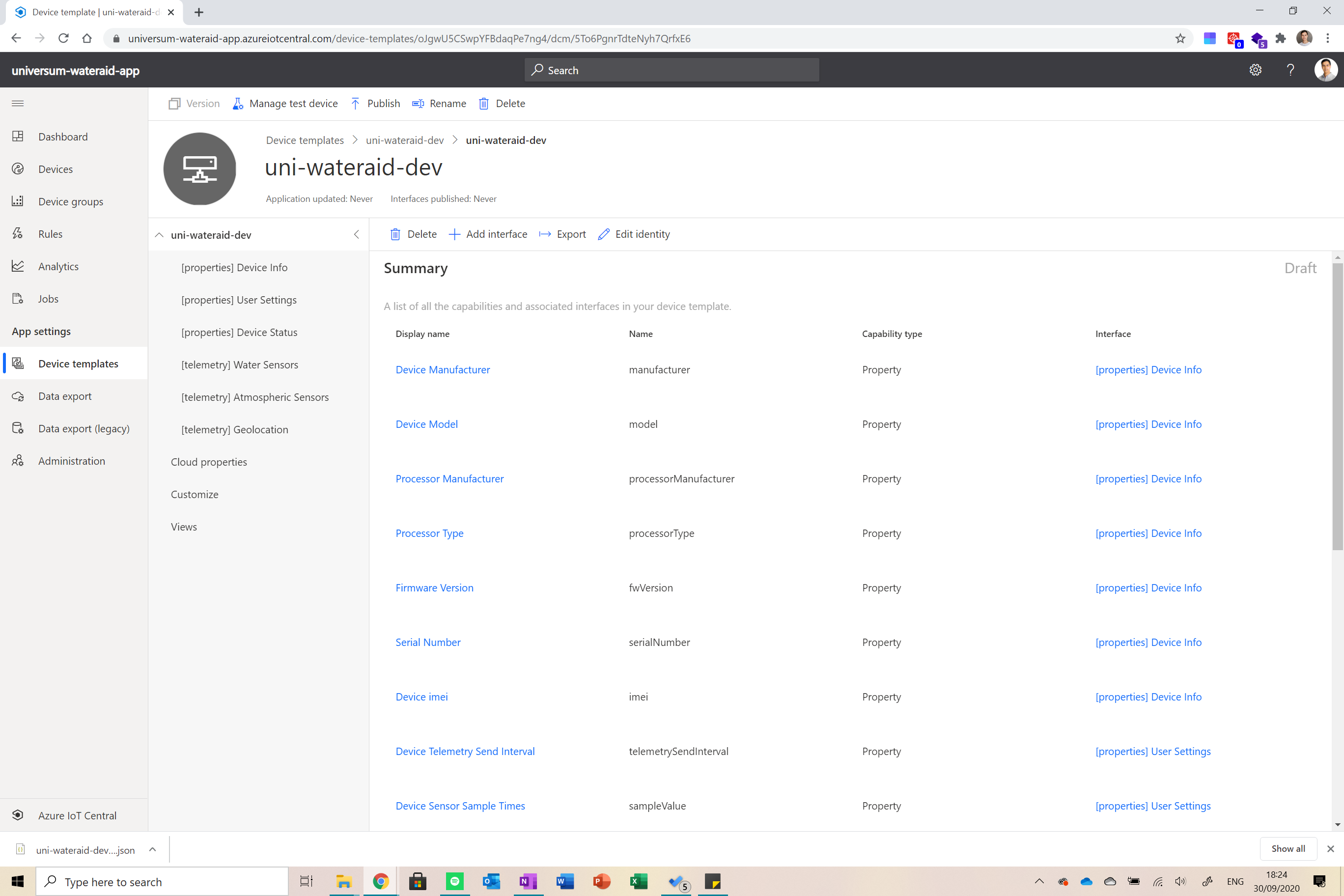
Next, click on the device name and select the Import Interface option. Now from the GitHub repo for the project (pull it if you have not already), go into the Backend folder and import the uni-wateraid-dev.json file. This should import all fields for you. You should end up with something similar to the image below.
![]()
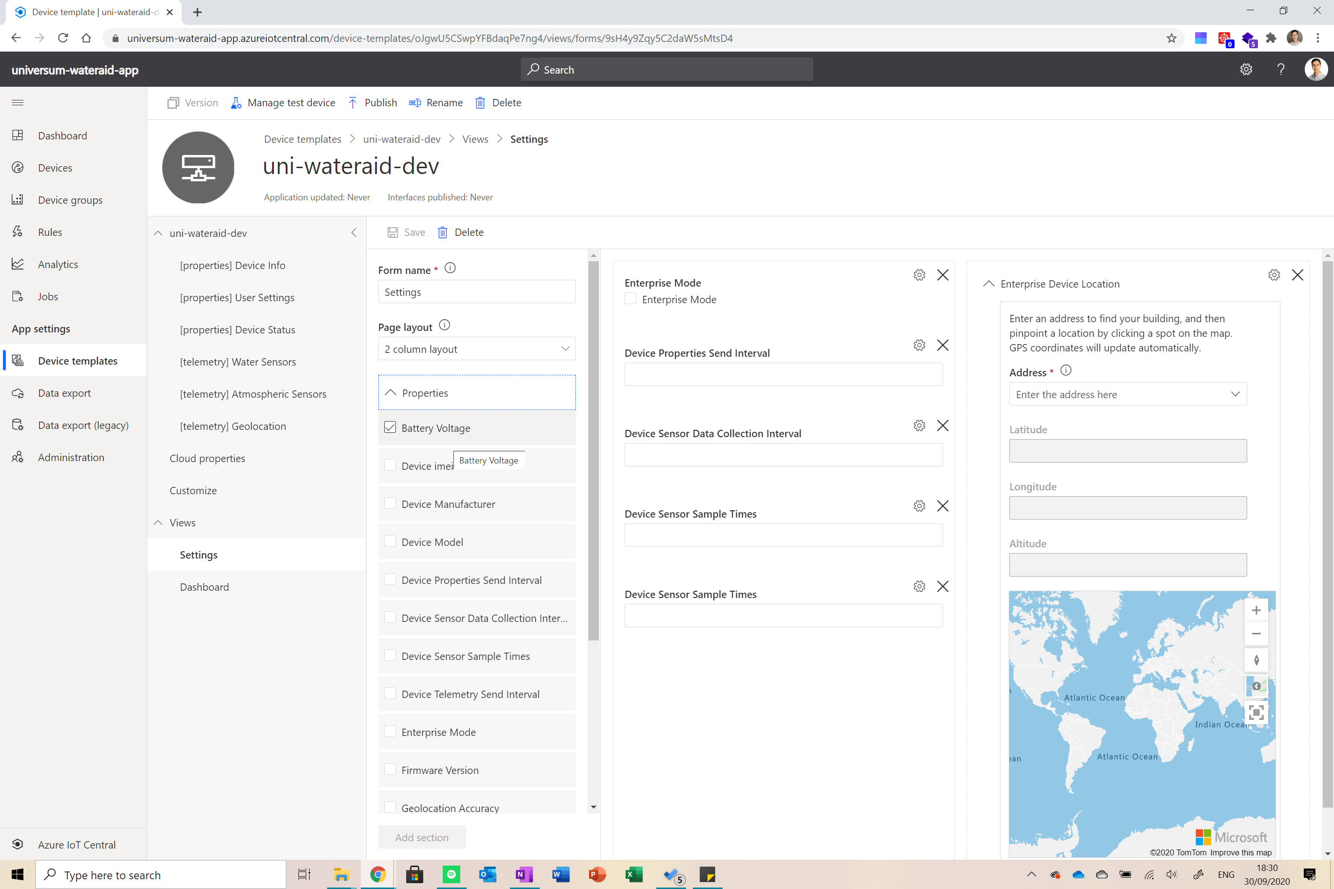
Next click on the views option from the menu on the left and create a new view called Settings. Here we will put all the twin properties so we can easily edit them from a centralised place (chose the edit properties option for the type of view). It should look something like this.
![]()
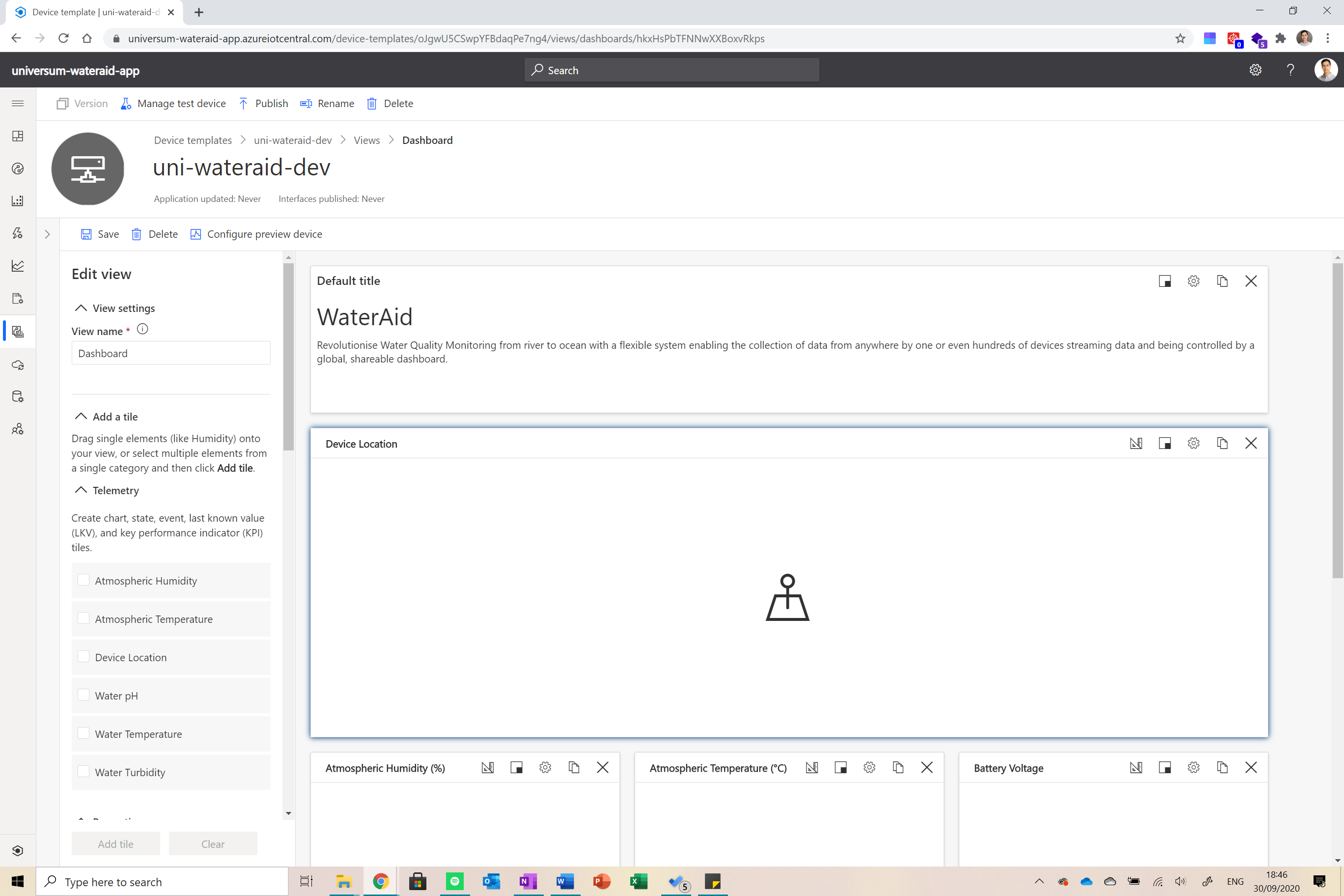
Now create a new view for the data streamed by the device (using the visualising the device option). Drag and drop the geolocation card, all sensor readings and battery and location precision onto the canvas. It should look something like this at the end (I also added mark-up).
![]()
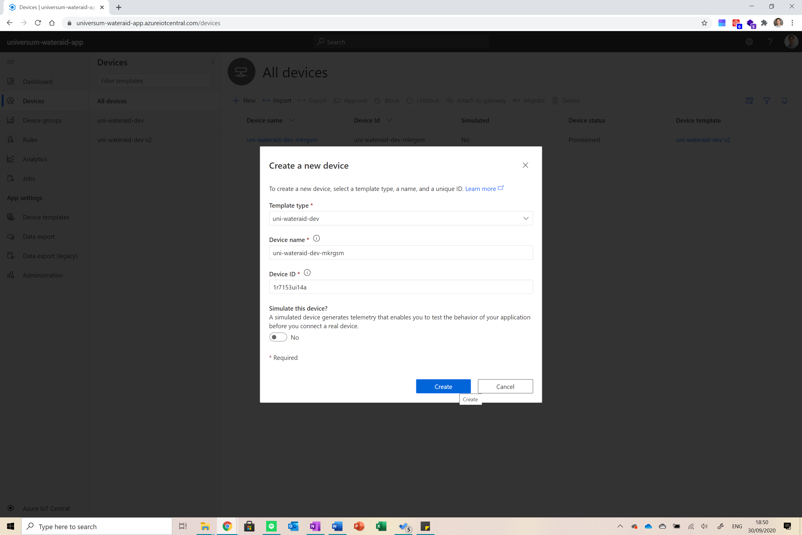
Finally, click on the publish button at the top of the screen and follow the instructions to publish the device template. Now go into the devices tab from the menu on the left and create a new device by pressing the plus icon. Set the details as shown in the image below.
![]()
And that’s it, you are ready to move on!
-
5Setting up the MKR GSM
I want to say a big thank you to Ian Hollier and Benjamin Cabé on GitHub for providing the libraries that I used to build this project. Their code is open source and available here. Anyways, before we move on, please install the following Arduino libraries.
- MKRGSM
- Arduino_MKRENV
- RTCZero
- PubSubClient
- ArduinoHttpClient
We need to increase the payload size limit in PubSubClient to allow for the larger size of MQTT messages from the Azure IoT Hub. Open the file at %HomePath%\Documents\Arduino\libraries\PubSubClient\src\PubSubClient.h in your favorite code editor. Change the line (line 26 in current version):
#define MQTT_MAX_PACKET_SIZE 128
-
6Getting Credentials
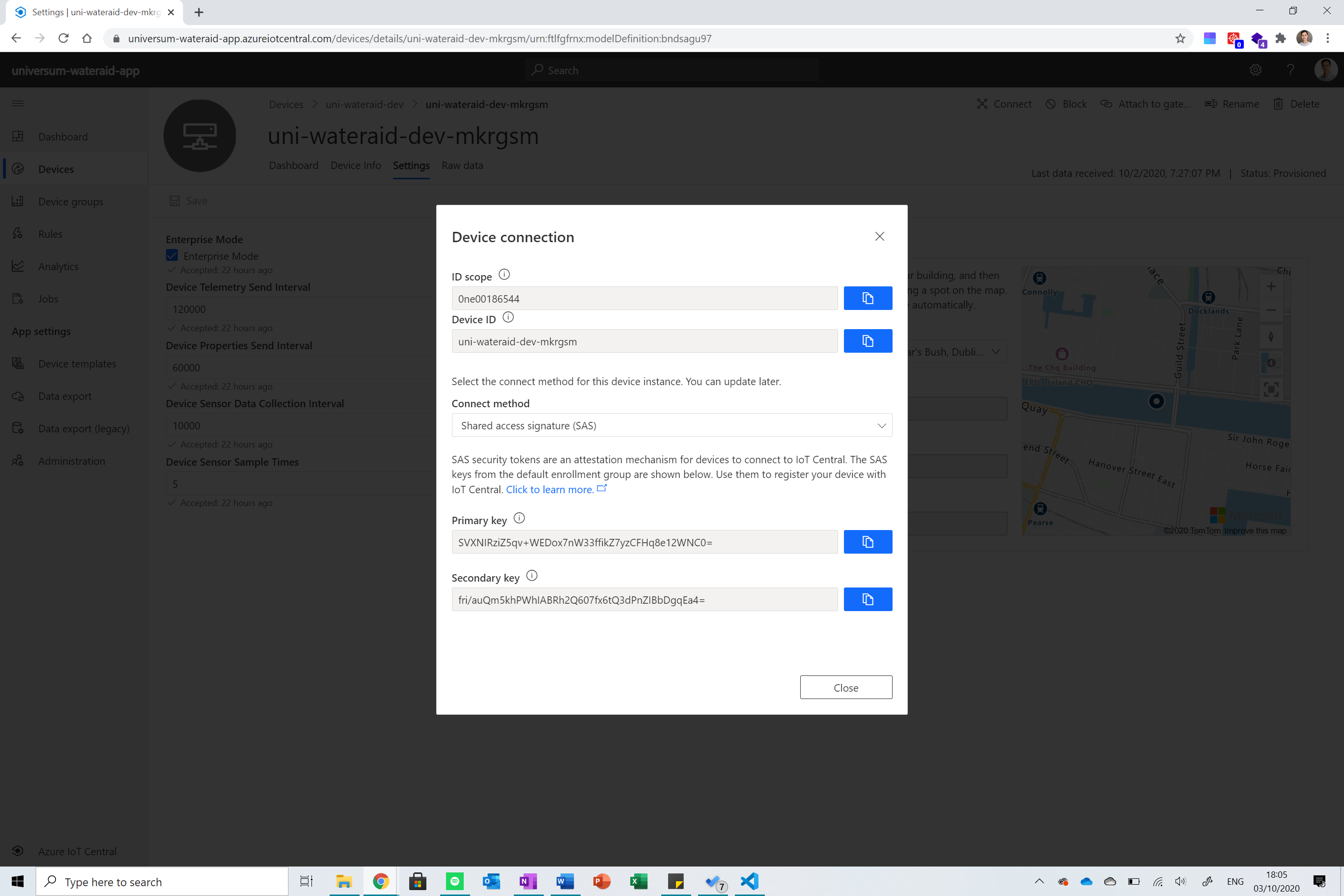
The next thing we need to do is get credentials to connect our application to IoT Central. To do this, please make sure you have the code open in Arduino IDE or your preferred editor. Ok, so the first thing you need to do is click on the device you just created. In the top right corner, there is a connect button, pressing it will reveal a bunch of credentials.
![]()
Copy the ID Scope into the iotc_scopeId variable under WaterAid/configure.h. Then copy the Device ID and paste it in iotc_modelId in the same file.
Finally, click out and select Administration from the menu on the left of the screen. From there, navigate to the Device Connection menu and click on SAS-Devices. From there you can copy the primary key displayed into the iotc_enrollmentKey variable in the file. And that’s it, you are done!
![]()
-
7Flashing the Code
![]()
Ok, so now that all of that is ready, you can save the sketch and flash the code onto the device. Make sure you have your SIM inserted and antenna connected. You can turn the serial monitor on to see debug.
-
8Making Sure Everything is working
![]()
It took me a long while to get things started. There was a lot of editing of libraries and Googling involved as documentation around connectivity was really limited to that one example above. But in the end everything worked. Below are some basic troubleshooting tips.
- Device stops before connecting to GSM? You may need to provide a PIN and password to use your SIM card (not if you use Hologram). You can check that out and set it up in WaterAid/gsm.h.
- Device stops while getting time? Error connecting to server. Look up other ways to get the time or another server to query it from.
- Device stops before connecting to IoT Central? If you are getting an error code in the serial monitor, you can look it up in connection to IoT Central. Out of my experience, a -5 and -2 are fixed by resetting the device. If you get something else, then either your connection or authentication is wrong. Try seeing if you can connect to other services (time, etc.) and recheck your credentials.
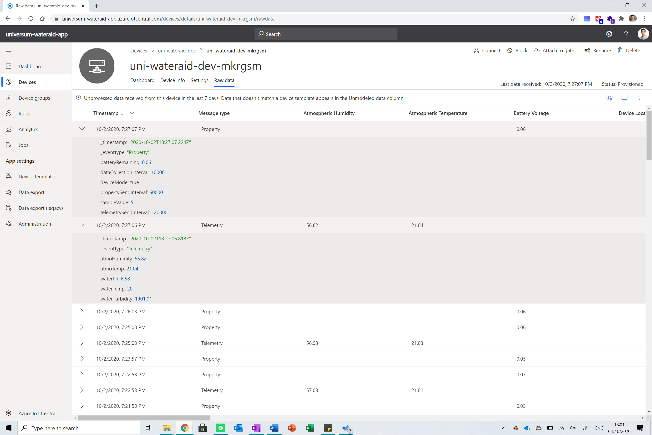
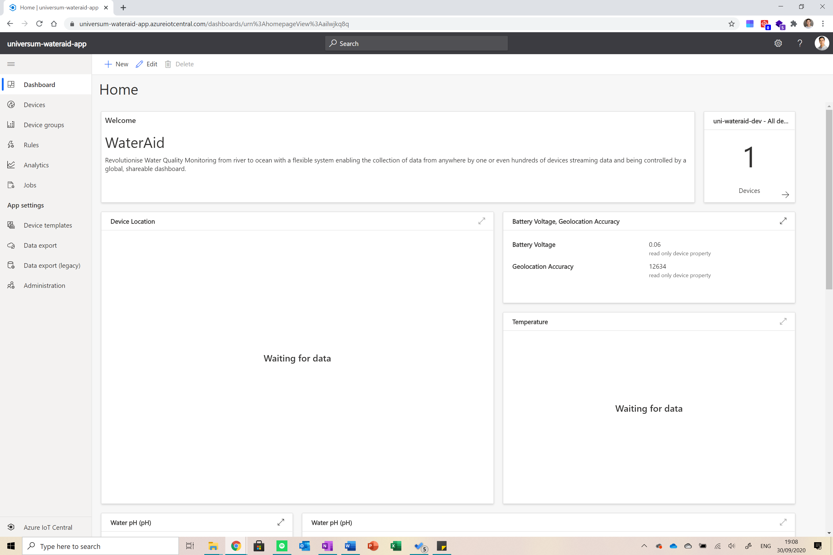
In the end, if everything works, you should see data appearing in the RAW data section of the dashboard as shown below.
![]()
And if you are really stuck, post a question on the project page and I’ll try my best to help.
-
9Building the Dashboard
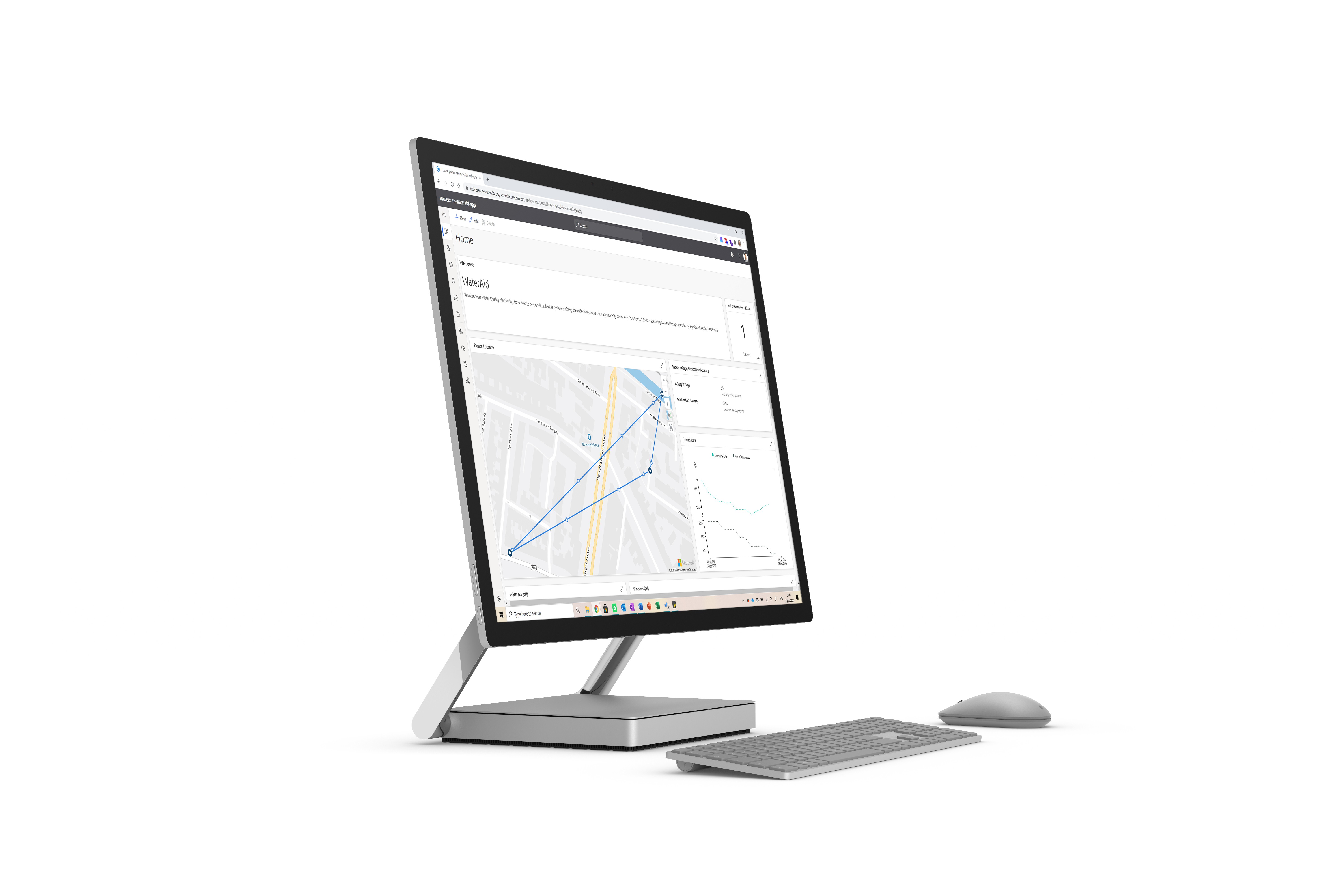
![]()
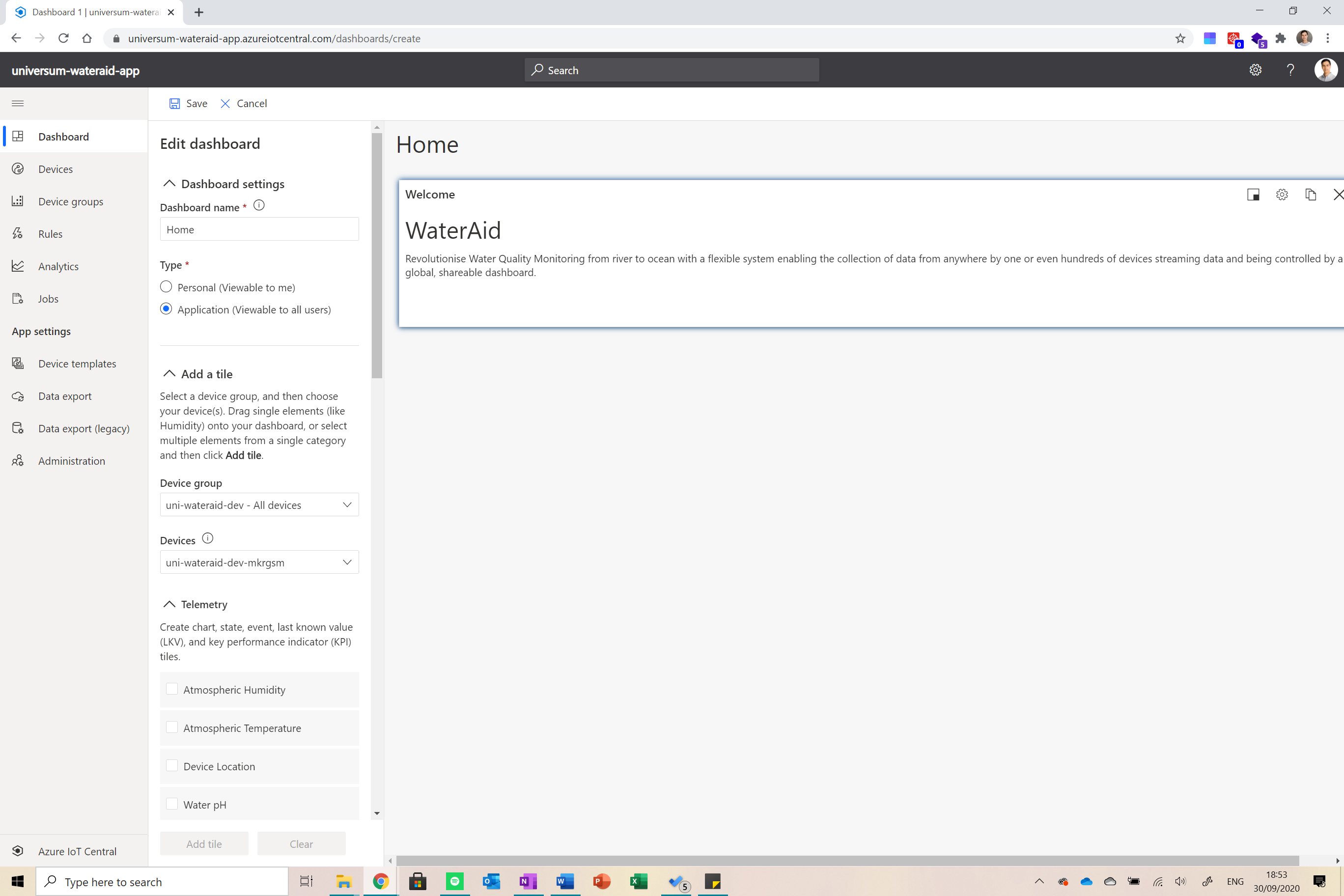
The dashboard is the place where all data collected by all devices is summarised. Go to the dashboard view on the IoT Central page and click the new button to create a new dashboard. Set the permissions according to your needs and then click create.
![]()
Now you want to add cards, graphs and maps to the dashboard summarizing all data. Select the device(s) you wish to display data from and then construct your visuals in accordance to your needs. Mine ended up looking like this.
![]()
-
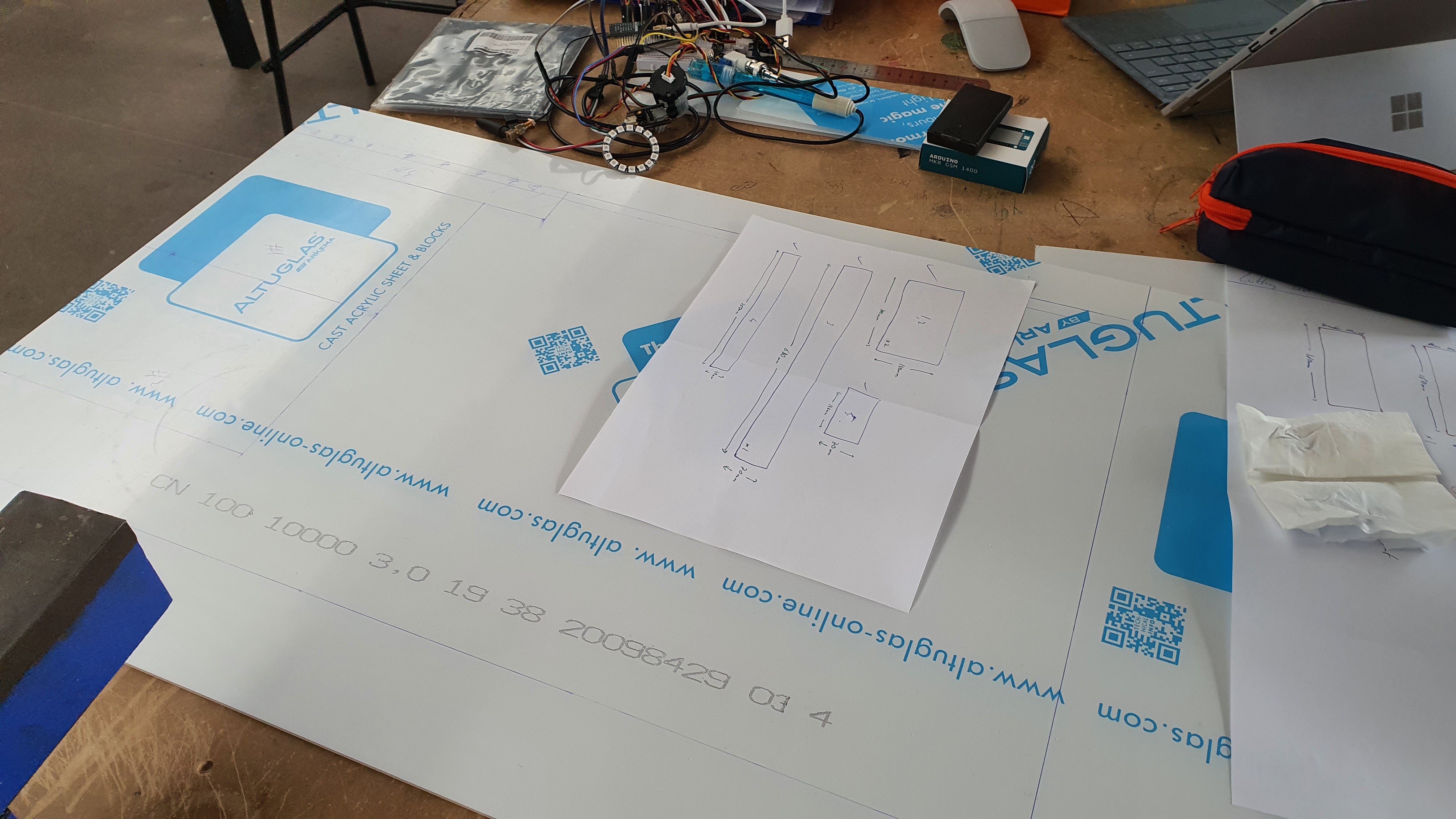
10Constructing the Enclosure
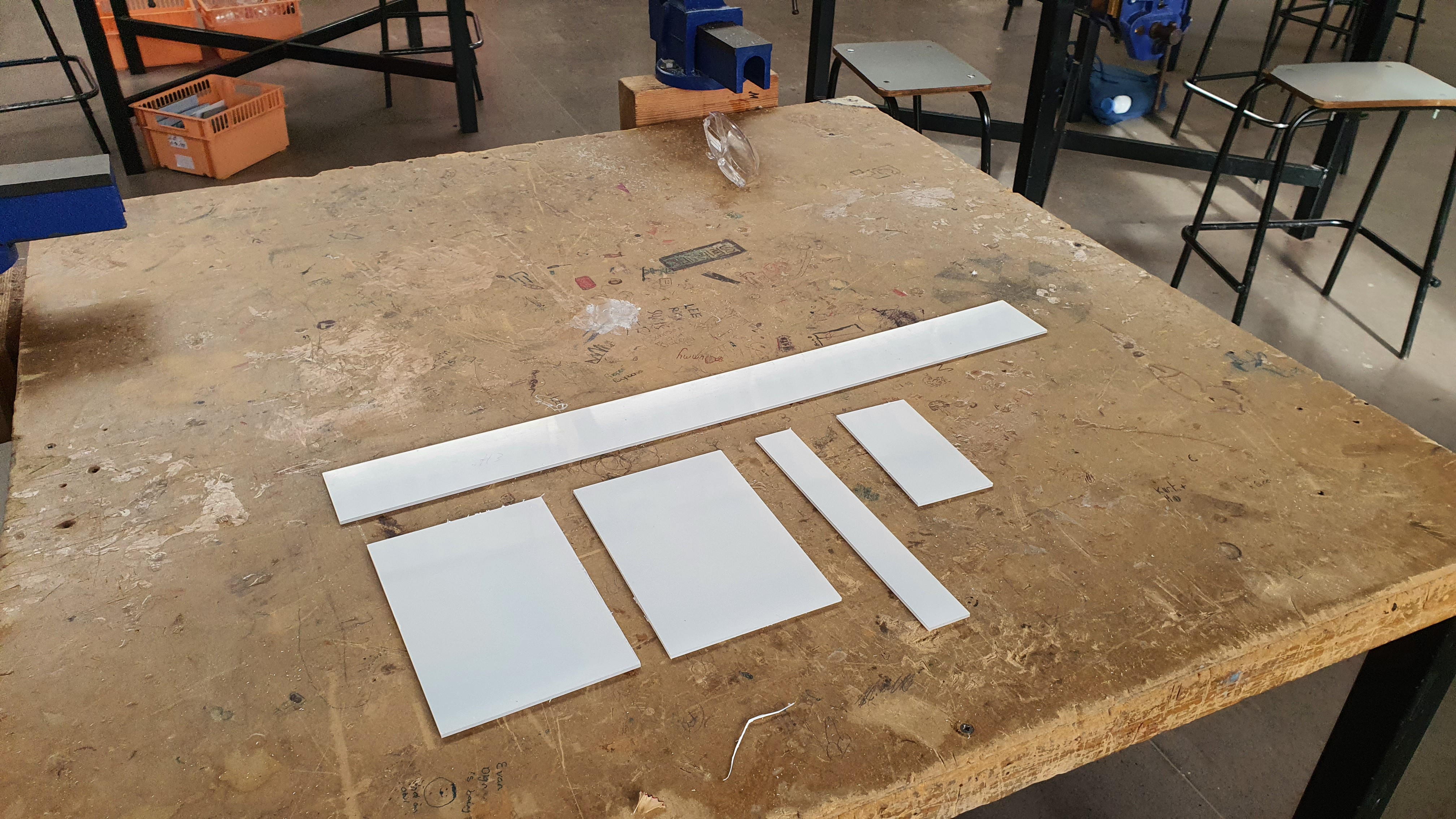
I started off with a large piece of plastic that I marked for cutting.
![]()
I then cut it into pieces using a band saw and sanded the edges making them soft.
![]()
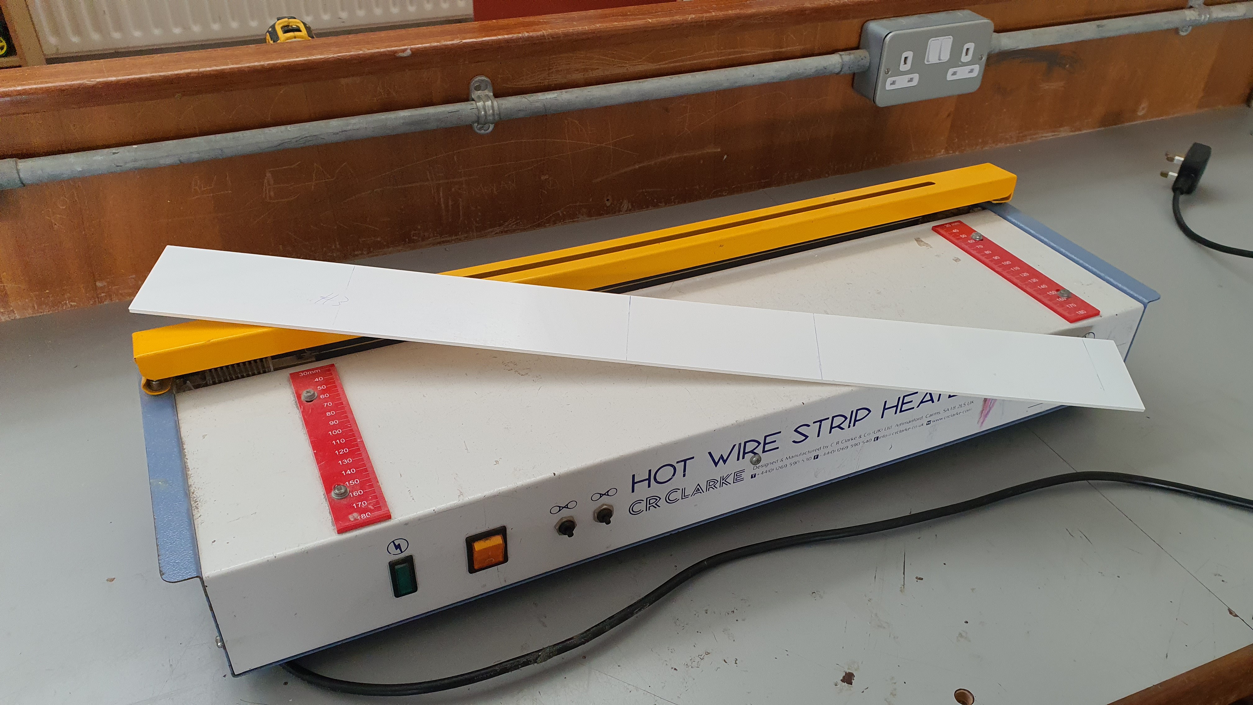
(don’t waste your time trying to decipher the drawings on the table, did this part in school) Anyways, I then bent the large piece into an open box using a hot wire strip heater and then brought the pieces home.
![]()
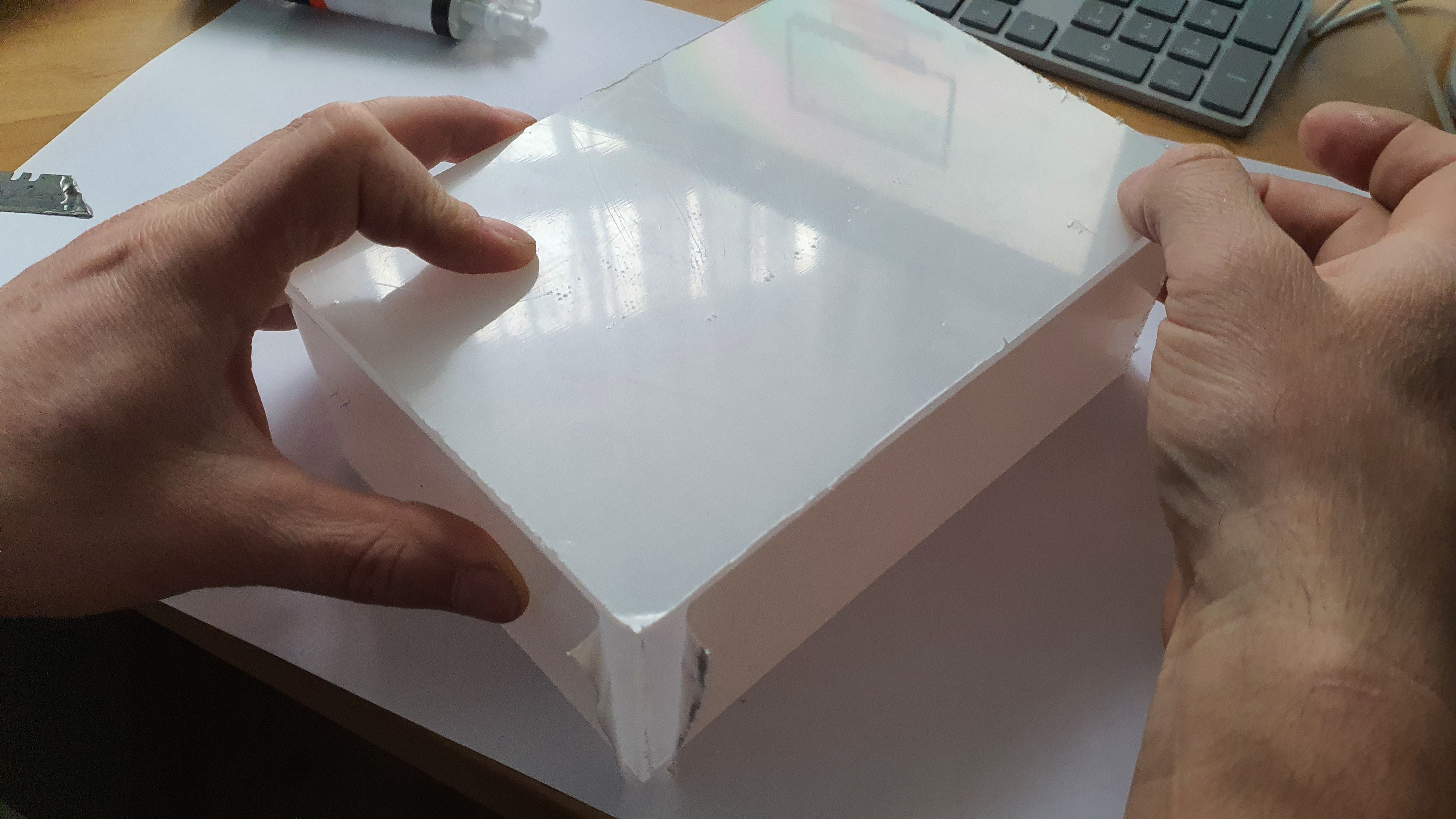
At home I started gluing the pieces together and then insulating them. I am no expert at this, so I let my dad take the lead (I designed the 3D drawing in the meanwhile). We then drilled holes in the enclosure (everything is in the STL file attached in the files section).
![]()
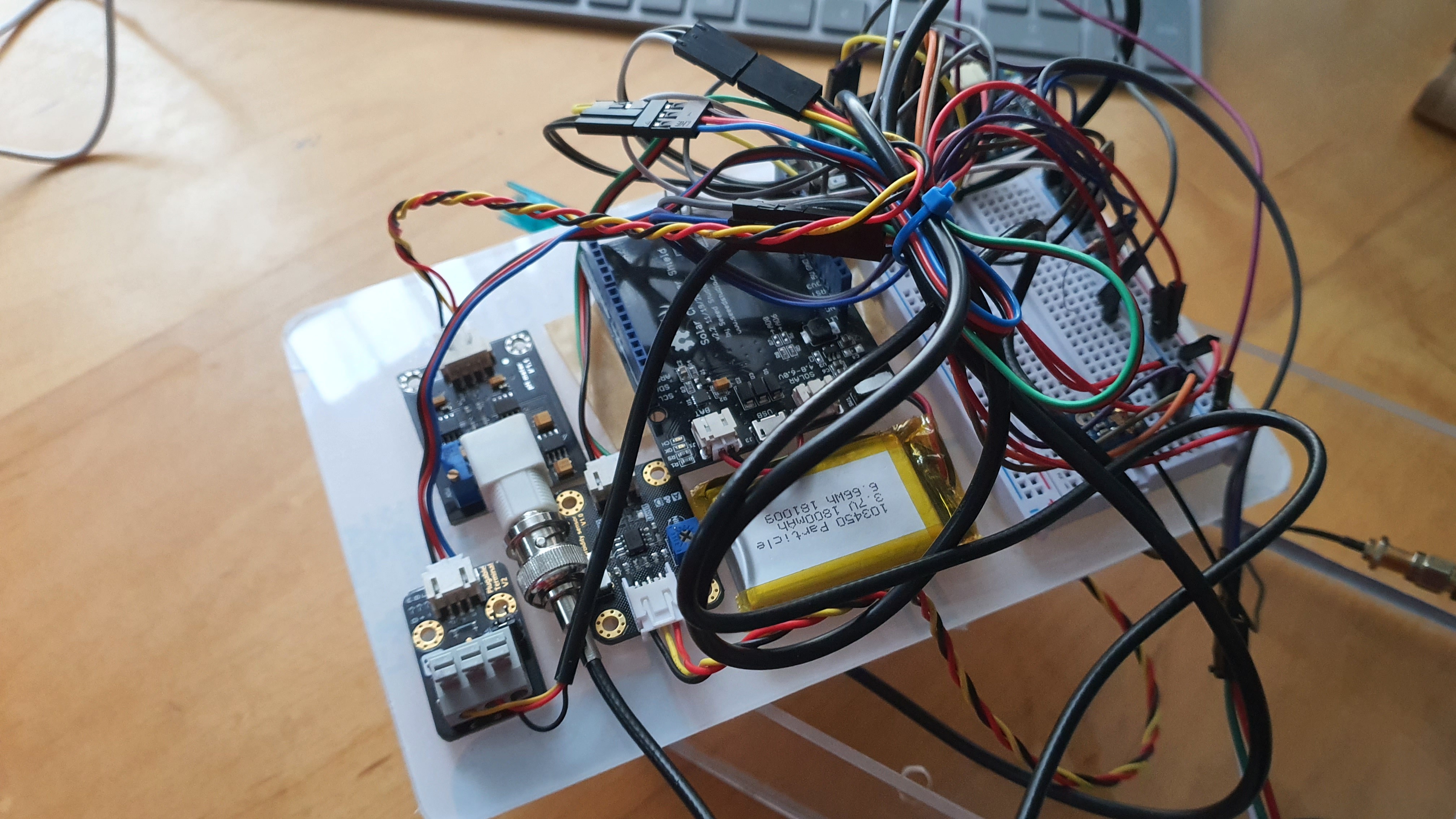
We then stuck the components to the enclosure using a variety of adhesive (primarily double sided tape as I did want to reuse the components I put in the project for other projects so being able to remove them was key).
![]()
And finally, we sealed it off and tested it to ensure that water could not get in. If you are building this and intend on distributing it, it is better to 3D print it, I unfortunately don’t have a 3D printer, so I had to manually make mine.
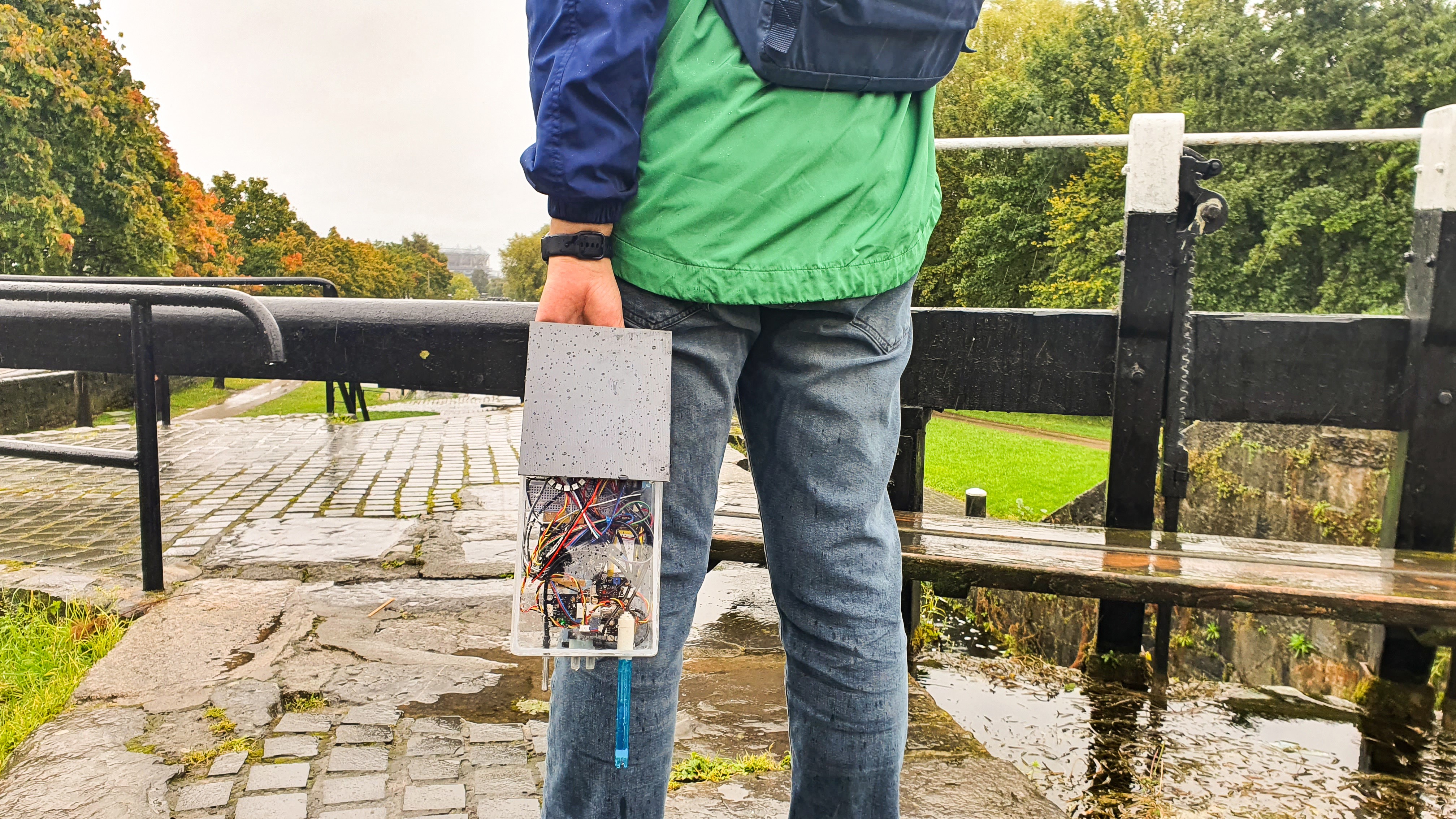
UnifiedWater
UnifiedWater is an IoT empowered, smart water quality monitoring device enabling remote data collection and visualisation on a dashboard.


Discussions
Become a Hackaday.io Member
Create an account to leave a comment. Already have an account? Log In.