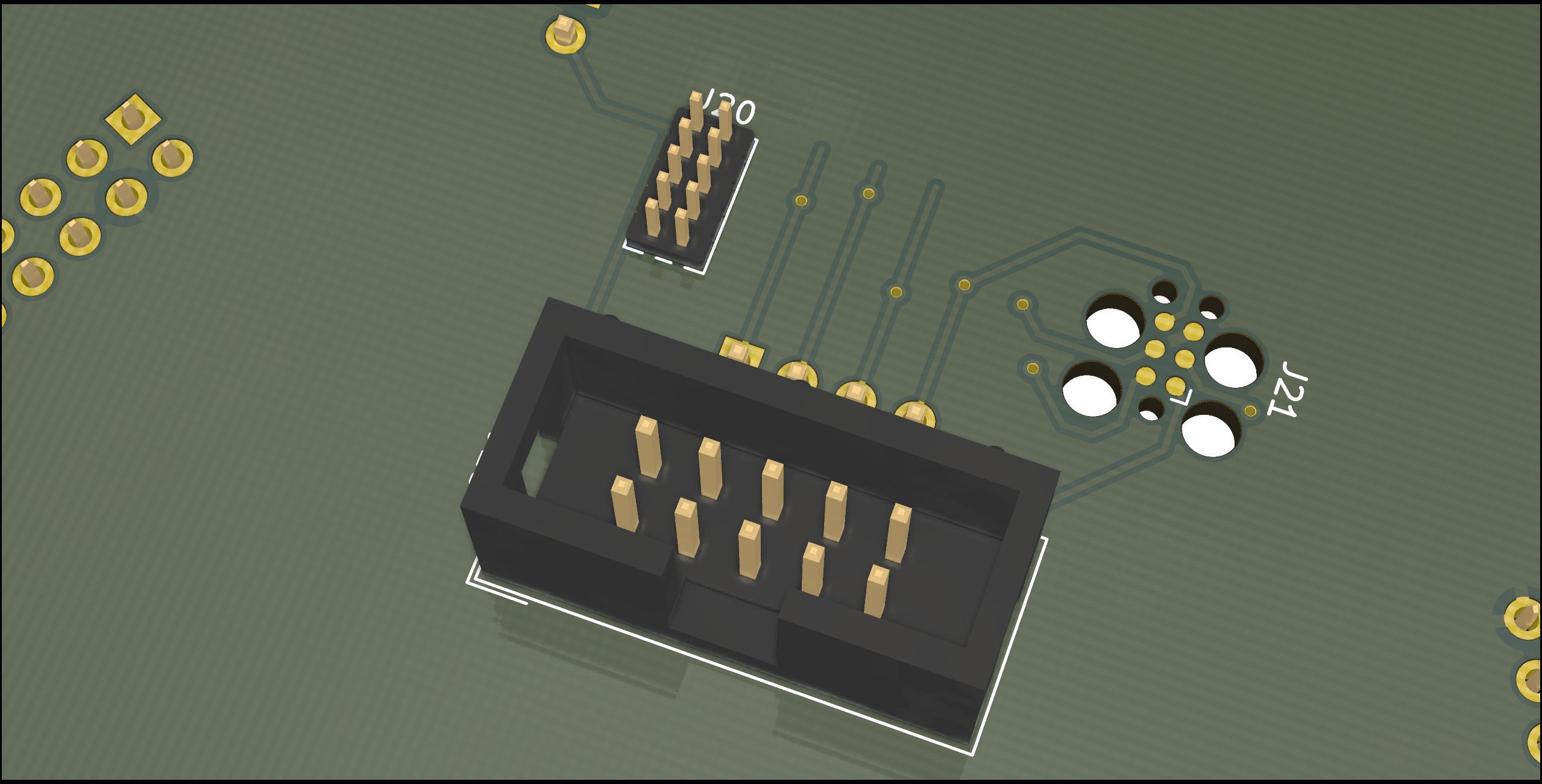
In the last log I discussed replacing the FTDI with an STM32. Both approaches have their advantages and drawbacks and based on personal experience one might prefer one over the other.
To address that I decides to implement the FTDI circuit alongside the STM32 circuit. Simply populate only the component of the debugger you want.
Gladly both ICs require resistors in series with the USB data lines. This means that we can use these as switches, which makes an USB switch obsolete. It also prevents long "stub traces", that could compromise the signal integrity through reflections.


Other people again might already have a favorite on-chip debugger dongle and want to use that. For that case I added the three most common programming headers I could think of. Name the ARM JTAG header with 0.1 and 0.05 inch pitch, as well as TC2030.

 marble
Discussions
Become a Hackaday.io Member
Create an account to leave a comment. Already have an account? Log In.