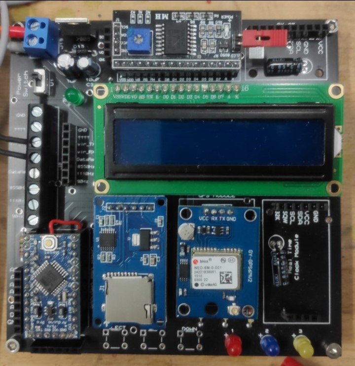
A custom datalogger was designed to record the data collected from the CBobby. The
datalogger was designed to verify the explosion detection ability of CBobby for long-term
(24- hours or more) operation. It will verify the data by comparing its recorded data with the
Zoom H2a audio recorder data. The data from the Daughterboard was sent to the datalogger
through serial communication protocol with a baud rate of 9600. This data consists of the
frequency band detections and the transient event detection pulses. To verify the data collected
from the data logger, an audio recorder was also connected with the microphone of the
CBobby. The datalogger and the recorder were synchronized by pulling up the transient
detector line and the microphone’s bias line high (after DC blocking capacitor) for a short
time or by creating a continuous loud noise for a couple of times (Clapping).
The datalogger has an I2C protocol based IMU (GY-80) and an LCD, SPI protocol-based
Memory (MicroSD card), and Real-time clock, and UART Serial communication-based GPS
module (Figure 7,8). The Arduino of the Daughter Board sends its data through the UART
based serial communication protocol to the virtual UART serial communicator of the
Datalogger. And the hardware-based UART communicator of the datalogger is connected to
the GPS module. Due to this reason, while programming the datalogger’s
microcontroller, the GPS module is needed to be disconnected.

 ifthekhar ahammad
Discussions
Become a Hackaday.io Member
Create an account to leave a comment. Already have an account? Log In.