ifthekhar ahammad
-
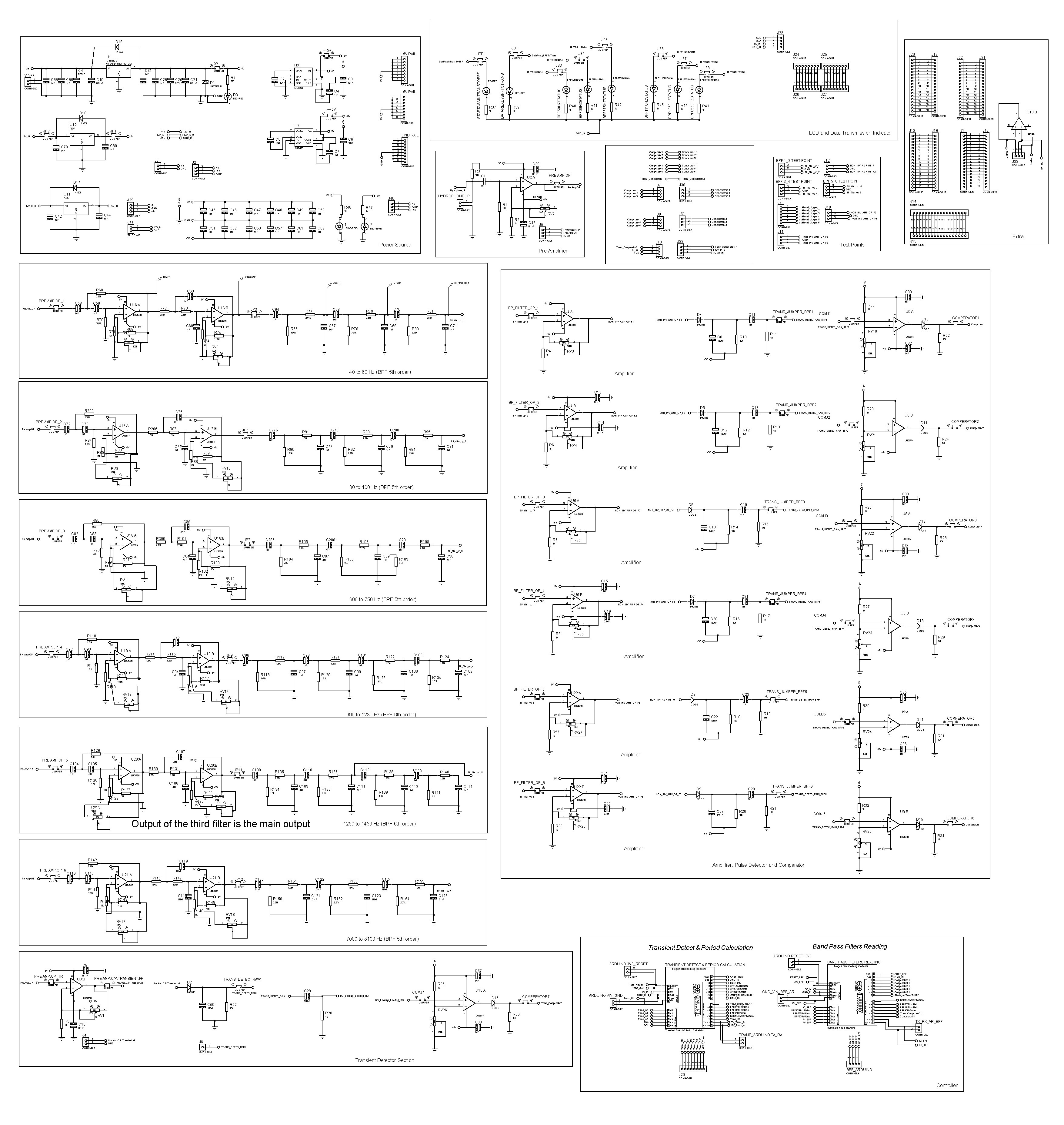
Combined MotherBoard and DaughterBoard Schematic
10/06/2020 at 10:03 • 0 commentsTo minimize the size of the design a new schematic was prepared to combine the MotherBoard and DaughterBoard but it still have not been produced because later on the Buffer section of the design was needed to be added and also for the final design, the prototyping features are also needed to be removed form the PCB. But this can be used to create the BOM of the current design (MotherBoard and DaughterBoard).
![]()
-
Demonstration Video
10/06/2020 at 02:44 • 0 comments -
Datalogger Schematic
10/06/2020 at 02:35 • 0 comments![]()
-
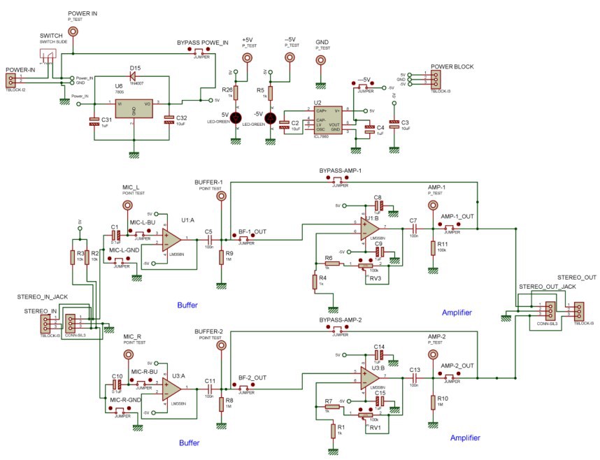
Buffer Circuit Schematic
10/06/2020 at 02:34 • 0 comments![]()
-
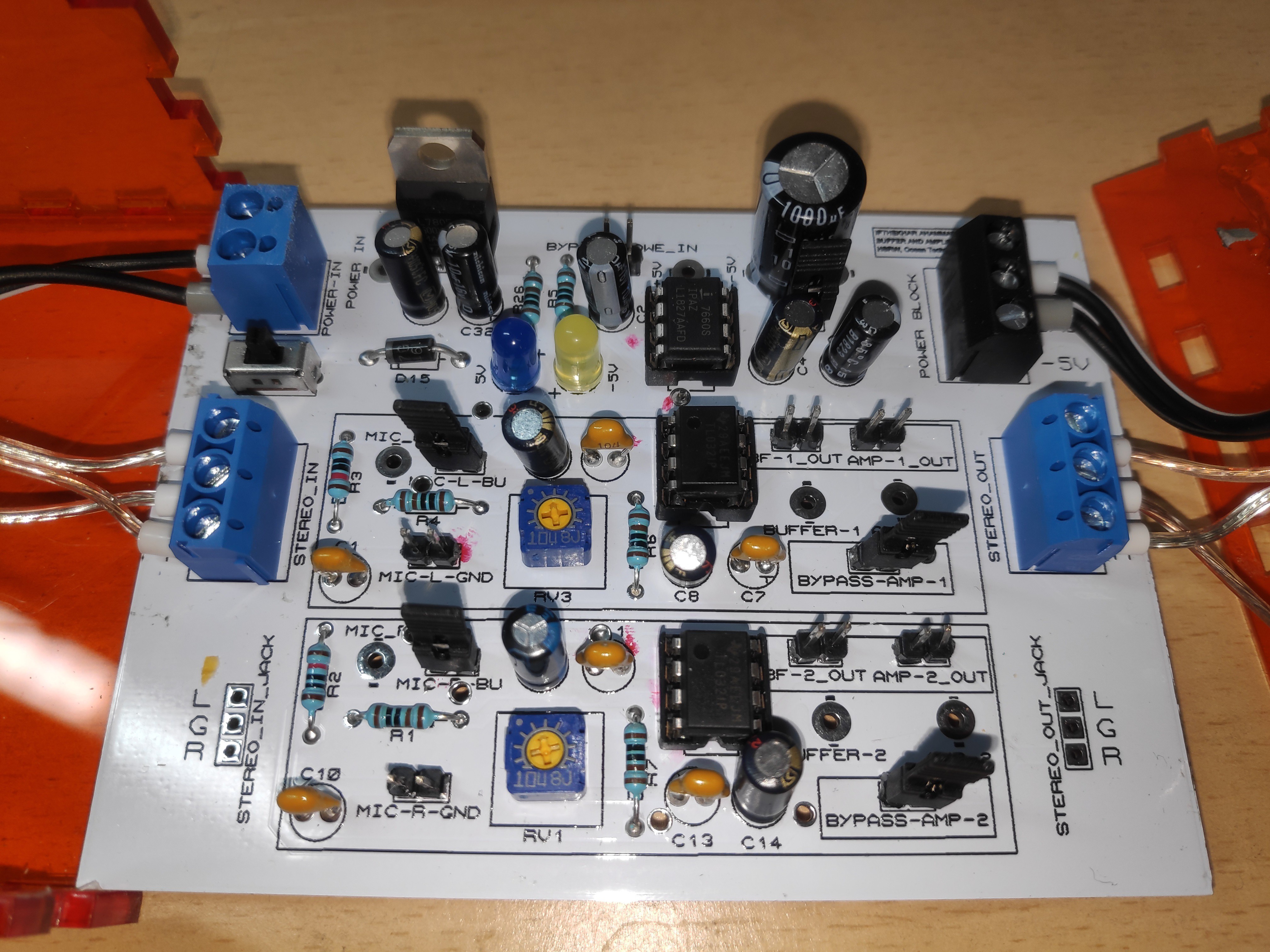
Buffer Circuit
10/06/2020 at 02:32 • 0 commentsDuring the initial test of the device, some variables had to be changed. For the field test, three
identical devices were made and due to that reason, two new hydrophones were needed as
well. After recording data with each hydrophone (9 meters long cable) with all three devices,
no noticeable loss of performance was observed. At one stage a decision was made to increase
the length of each hydrophone cable and one important property was overlooked, the new
cable that was used was made of few different materials and also had a thin layer of tissue
paper in between the jacket and the cables. That may have added some additional pyro-electric
activity and after connecting them to the existing cables, CBobby has recorded higher
noise activity. Based on the current perspective the added length (extra 30 meters to each
hydrophone cable) or the property of cable or both can be the reason for that noise activity.
To verify the detection ability and to monitor & record the acoustic activity, a Zoom H2a
recorder was also connected in parallel with the CBobby. Now the observed data from the
hydrophone was sent to both the H2a recorder and CBobby simultaneously. It
resulted in a lot of noise generation on both the recorder and the CBobby end. It also
dramatically reduces the amplitude of the received signal.
One reason for this is the crosstalk between the recorder and the CBobby and another reason
is the impedance mismatch. To solve the impedance match issue, An Operational Amplifier
based stereo buffer/Amplifier circuit has been implemented in the system separately. Where either the buffer or the amplifier circuit or both in conjunction can be used to
stabilize the microphone signal. But that approach did not solve the problem completely.![]()
-
The Datalogger
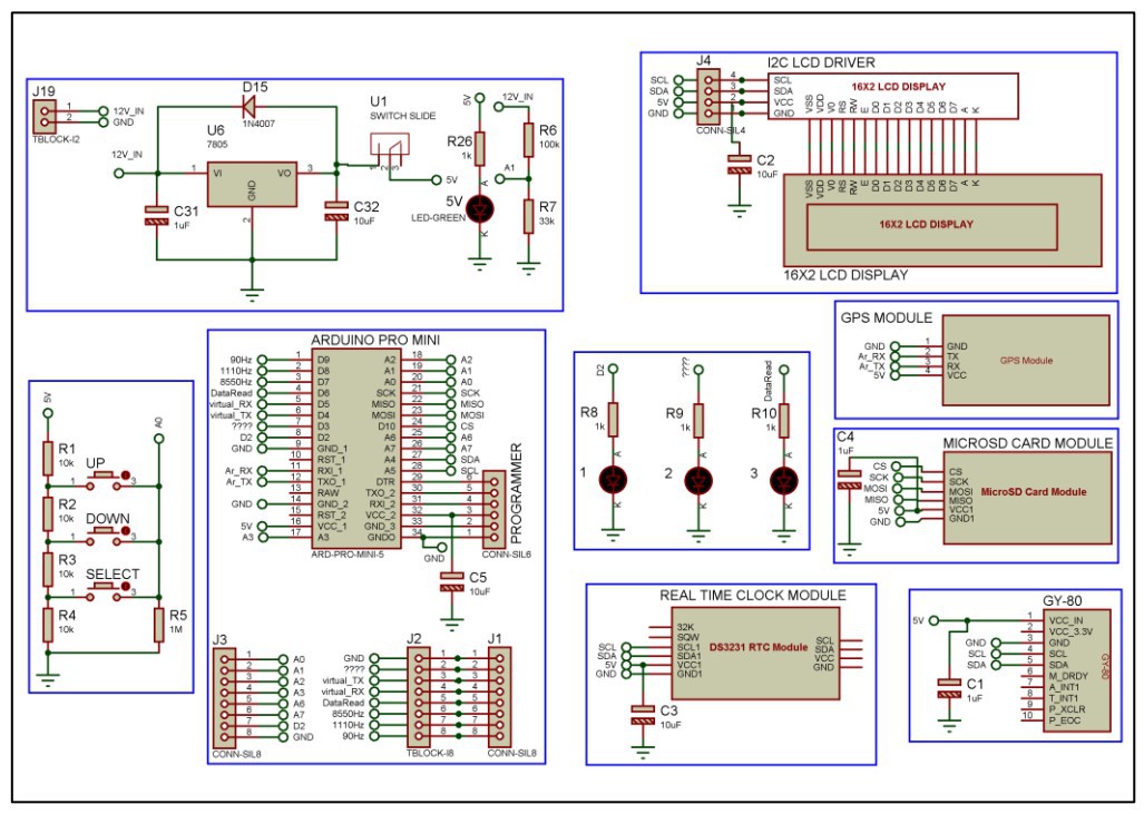
10/06/2020 at 02:28 • 0 commentsA custom datalogger was designed to record the data collected from the CBobby. The
datalogger was designed to verify the explosion detection ability of CBobby for long-term
(24- hours or more) operation. It will verify the data by comparing its recorded data with the
Zoom H2a audio recorder data. The data from the Daughterboard was sent to the datalogger
through serial communication protocol with a baud rate of 9600. This data consists of the
frequency band detections and the transient event detection pulses. To verify the data collected
from the data logger, an audio recorder was also connected with the microphone of the
CBobby. The datalogger and the recorder were synchronized by pulling up the transient
detector line and the microphone’s bias line high (after DC blocking capacitor) for a short
time or by creating a continuous loud noise for a couple of times (Clapping).
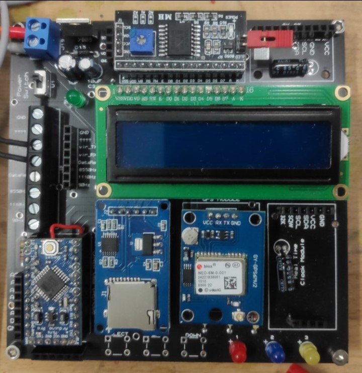
The datalogger has an I2C protocol based IMU (GY-80) and an LCD, SPI protocol-based
Memory (MicroSD card), and Real-time clock, and UART Serial communication-based GPS
module (Figure 7,8). The Arduino of the Daughter Board sends its data through the UART
based serial communication protocol to the virtual UART serial communicator of the
Datalogger. And the hardware-based UART communicator of the datalogger is connected to
the GPS module. Due to this reason, while programming the datalogger’s
microcontroller, the GPS module is needed to be disconnected.![]()
-
Calibration outcome
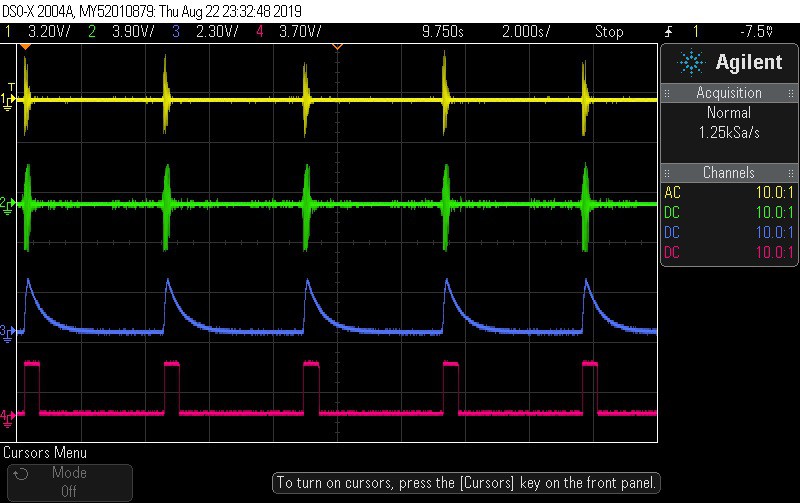
10/06/2020 at 02:22 • 0 commentsCalibration outcome of a single channel:
![]()
Figure 25: Signal processing of one of the frequency bands (After Pre-Amplification and filter section (yellow), Amplification stage (green), BWPC stage (blue) and LLC stage (magenta))
-
Primary calibration
10/06/2020 at 02:18 • 0 commentsThe environmental condition of different locations will be different and based on the shallowness of water, underwater habitat, water temperature and distance from the explosion, etc., the calibration of the device will change but for the primary test condition the whole system will have a fixed sets of parameter and only the gain of the pre-amplifier will vary (motherboard), and this method of calibration will be put on to the trial at the actual field test. So, to achieve this single variable-based calibration process, the following steps were taken:
- From the function generator, the amplitude of the test signal (sinusoidal wave) has been set to 100mVp
- Set the Pre-Amplifier output to 1V
- Set all the amplifiers (only for ASA) output to 2V
- Set all the LLC’s threshold voltage to 600mV (Positive level detector, threshold value)
-
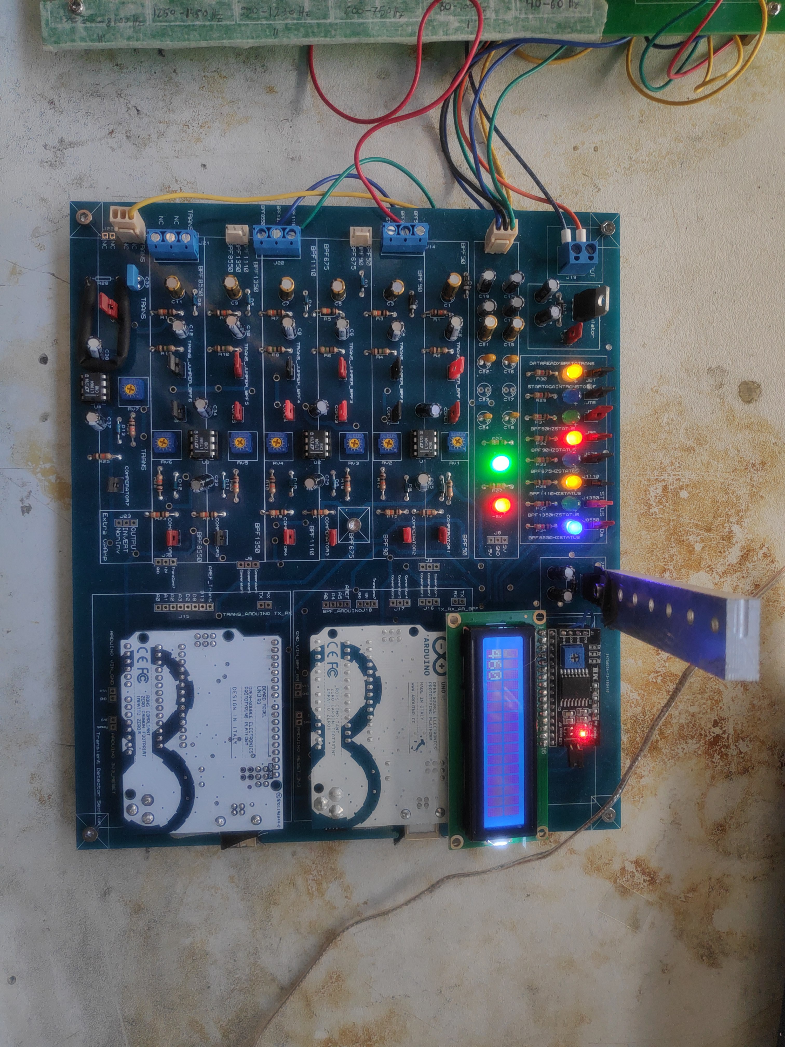
DaughterBoard PCB
10/06/2020 at 02:13 • 0 commentsThe DaughterBoard pcb was prepared.
![]()
-
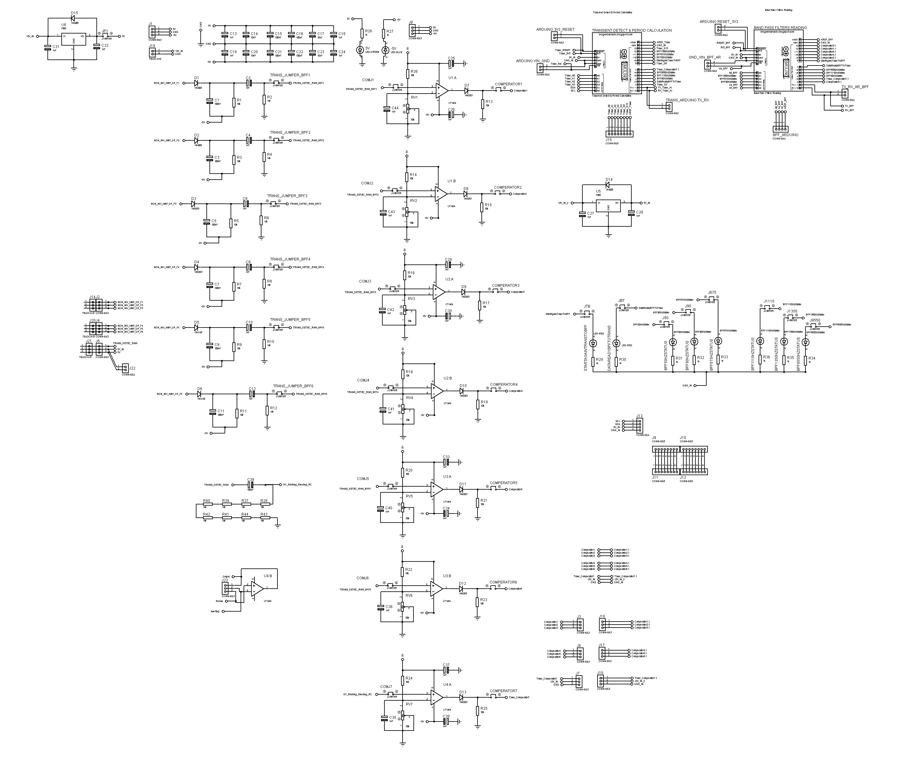
DaughterBoard Schematic
10/06/2020 at 02:09 • 0 commentsWhen the DaughterBoard Prototype was performing properly the proper schematic of the DaughterBoard was prepared with all the necessary prototyping features such as arduino connection and indicator LEDs
![]()
CBobby
Design and Development of an Underwater Explosion Detection Robot for Monitoring Dynamite Fishing in the Philippines