Dual CAN Motor Controller Redesign
While most of the V1.0 dual CAN motor controller works, the CAN interface does not. In addition, there were a number of usability improvements I wanted to make for a V1.1 update. I used JLCPCB as the assembly service, and EasyEDA for its clean interface to that assembly service. Their assembly service only supports a limited number of components and only single-sided SMD parts. Therefore I will assemble all the through hole parts myself.
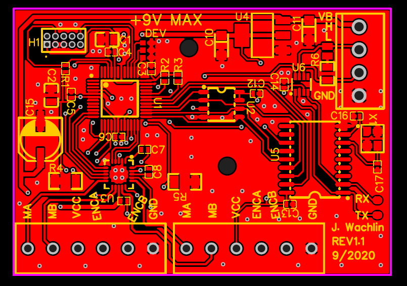
The updates were:
- Add a 16MHz crystal to the MCP2515 to fix the CAN issue
- Add pads at logic level CAN TX/RX for debugging support
- Label all external connections on silkscreen
- Label maximum input voltage
- Add optional CAN 120 Ohm termination resistor with solder jumper
- Add 3-bit device numbering with solder jumpers to address devices without firmware changes
- The first version just used 0.1" pitch through holes for the motor and power/CAN connections. On V1.1 I chose actual screw terminal connections so wires don't need to be soldered permanently in
- Add holes that can be used for mounting
- Add bulk capacitance for motor controller (doesn't seem strictly necessary, but not a bad idea to have)
The PCB got slightly larger due mainly to the larger external connectors. The image below shows the updated layout. PDFs of the layout and schematic have also been uploaded to the project page.
Main Robot Controller
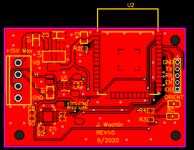
These dual motor controllers are meant to be peripherals on a larger network. They receive higher level commands from some external device over CAN, and handle the low-level motor control. I therefore built an example simple main controller. The main requirements are an attitude sensor and sufficient computational capability to theoretically run complex walking gait controllers.
For this design I used the ESP32. With 2 cores at 240MHz, it has the computational capability to run fairly complex control schemes. It also has a built in CAN controller. Finally, it supports wireless connectivity so I can send commands remotely if desired. I also used the MPU6050 as an attitude sensor. I can either use its internal sensor fusion, or write my own Kalman filter to fuse the accelerometer and gyroscope data.
Just like the dual motor controller, I made sure to label all external pins, add CAN TX/RX pads for debugging, as well as I2C debugging support. It has 2 LEDs which tentatively will indicate when it has good wireless communication and when it has a good orientation estimate.
Thanks to JLCPCB's insanely cheap assembly service, I bought 10 of each board for ~$200 total. Getting each board nearly fully built and delivered in <2 weeks for ~$10/board is crazy!
Discussions
Become a Hackaday.io Member
Create an account to leave a comment. Already have an account? Log In.