Hardware
The new version of the motor controller and the first version of the ESP32-based main controller arrived this week, and I've been testing them out. The hardware turned out nicely. The screw terminals and better labeling all help the design look more professional.
The ESP32-based main controller is shown below. It is a simple board, with the ESP32 for computation and wireless communications, a MPU6050 IMU, and a CAN transceiver.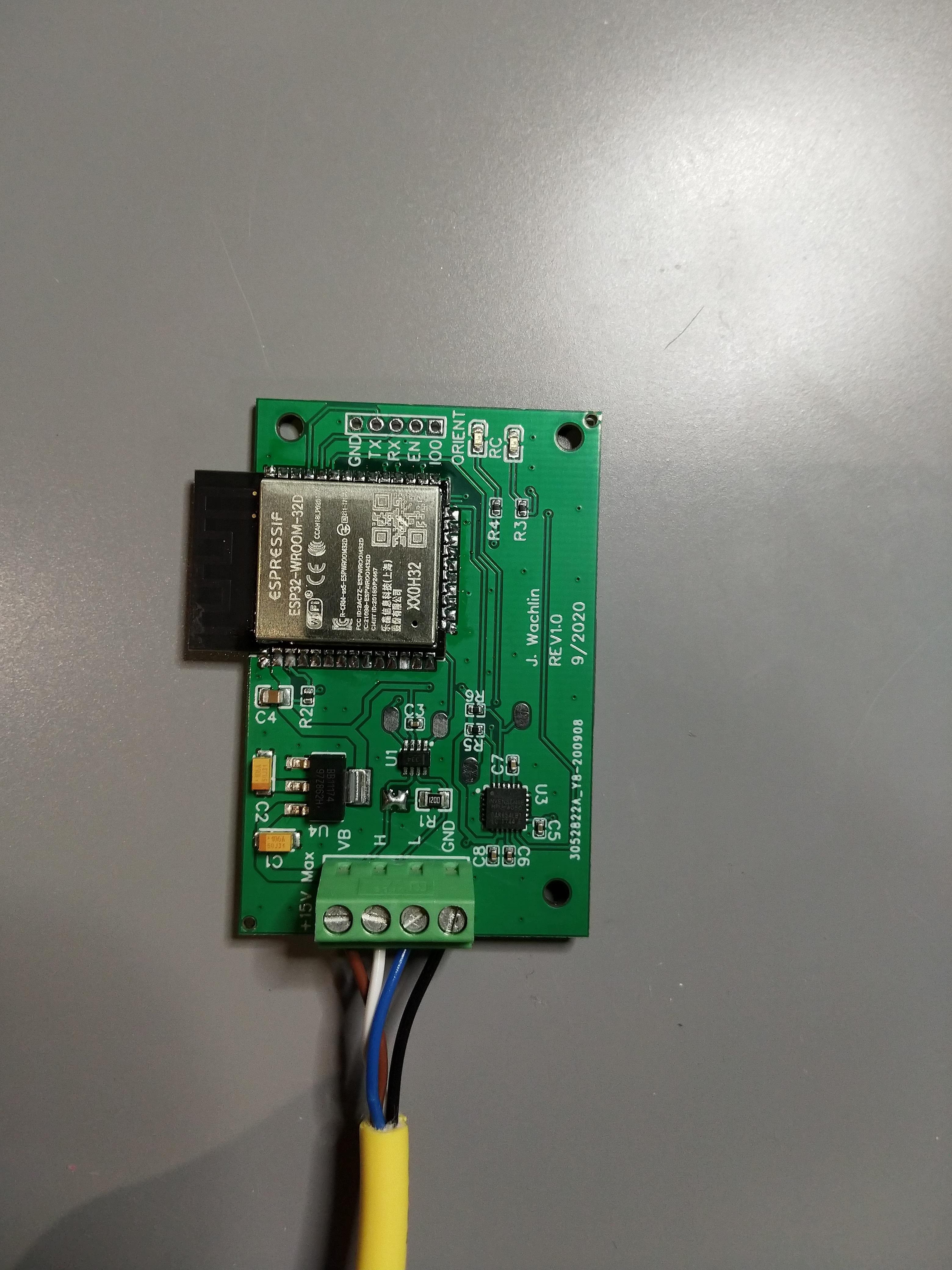
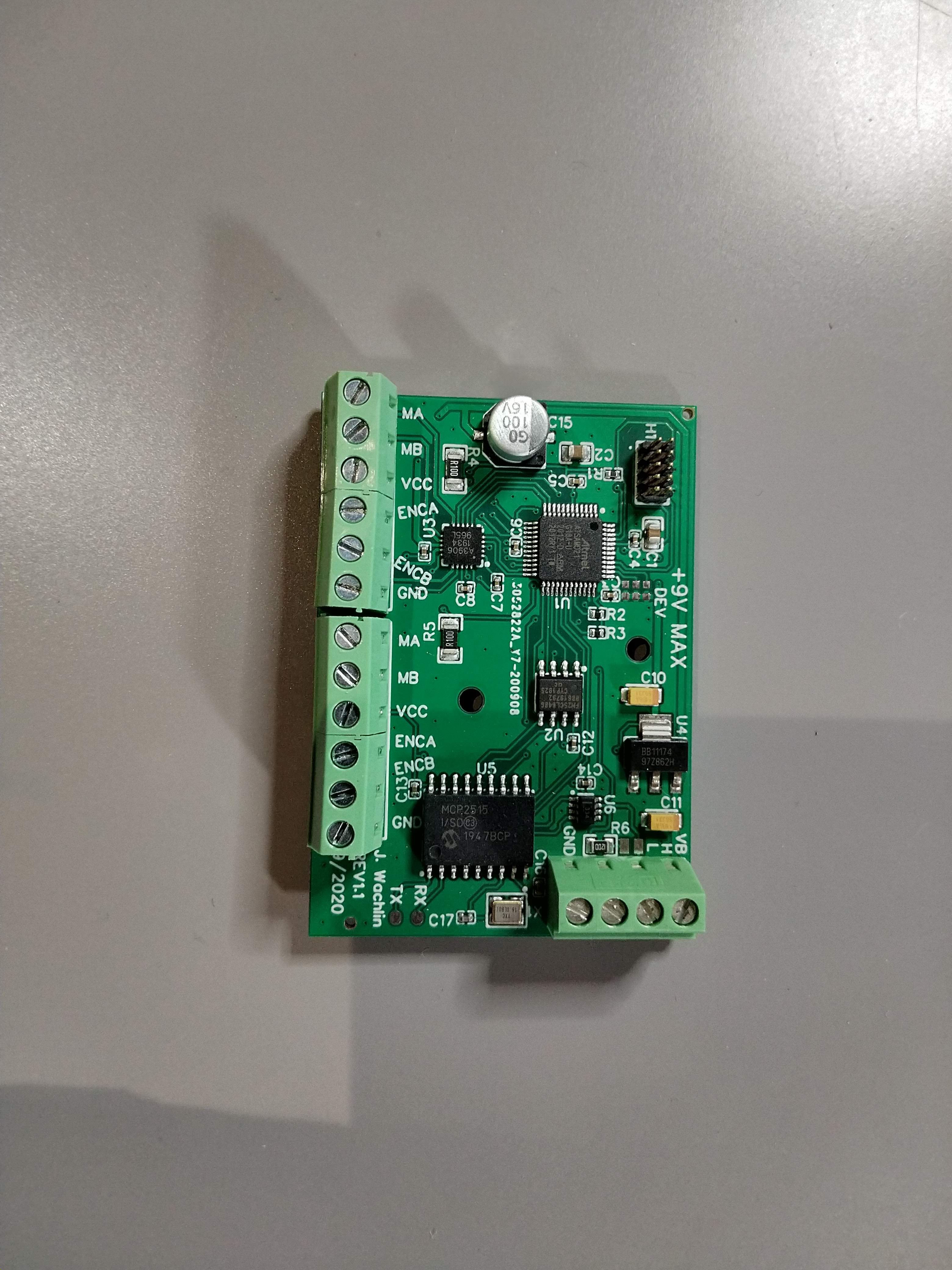
Next, let's look at the Rev 1.1 motor controller. The screw terminals and bulk capacitor are the most obvious changes, but the most important update is the 16MHz crystal added to the MCP2515 CAN controller.
Networking
With a main controller, and working CAN controller on the motor controller, I was able to move forward with the CAN communication layer. In a previous log, I explained how we split the bits of the frame IDs to indicate different messages. I also said the network would run at 500kbps. However, I bumped that up to 1Mbps, because why not? I added a software timer to send motor telemetry at 20Hz. For now, this is the motor position and current, but I plan to add more information in the future.
I also added more support for various control schemes. Each received CAN frame is put onto a FreeRTOS queue, and parsed in the CAN bus task. For each different received control command, the control approach is changed, so that the main controller can switch from closed loop position commands to open loop duty cycle commands without issue.
The video below shows the first time the networking was working. The main controller was sending position commands, and the motor was moving correctly.
Unbelievably Dumb Demo
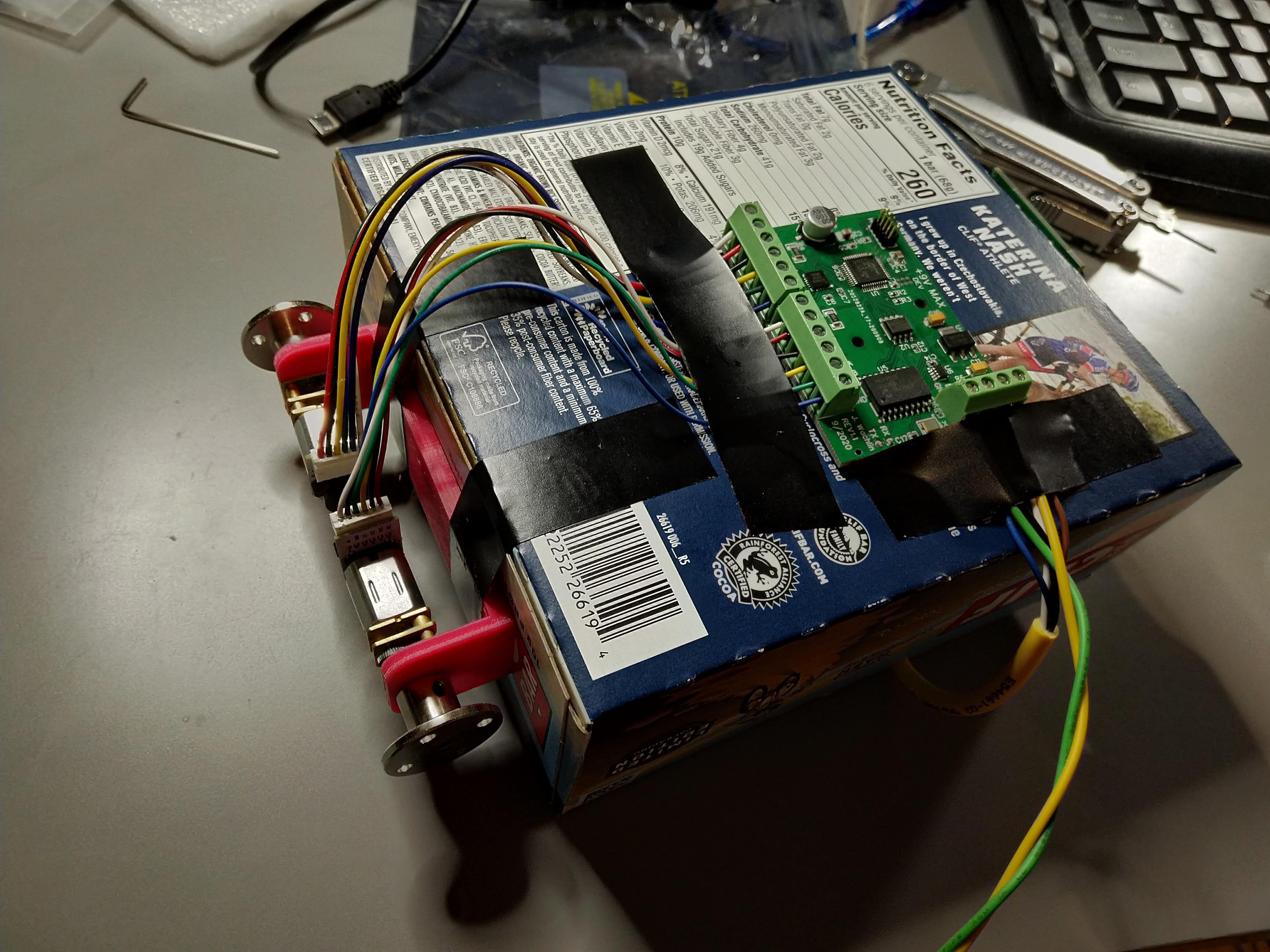
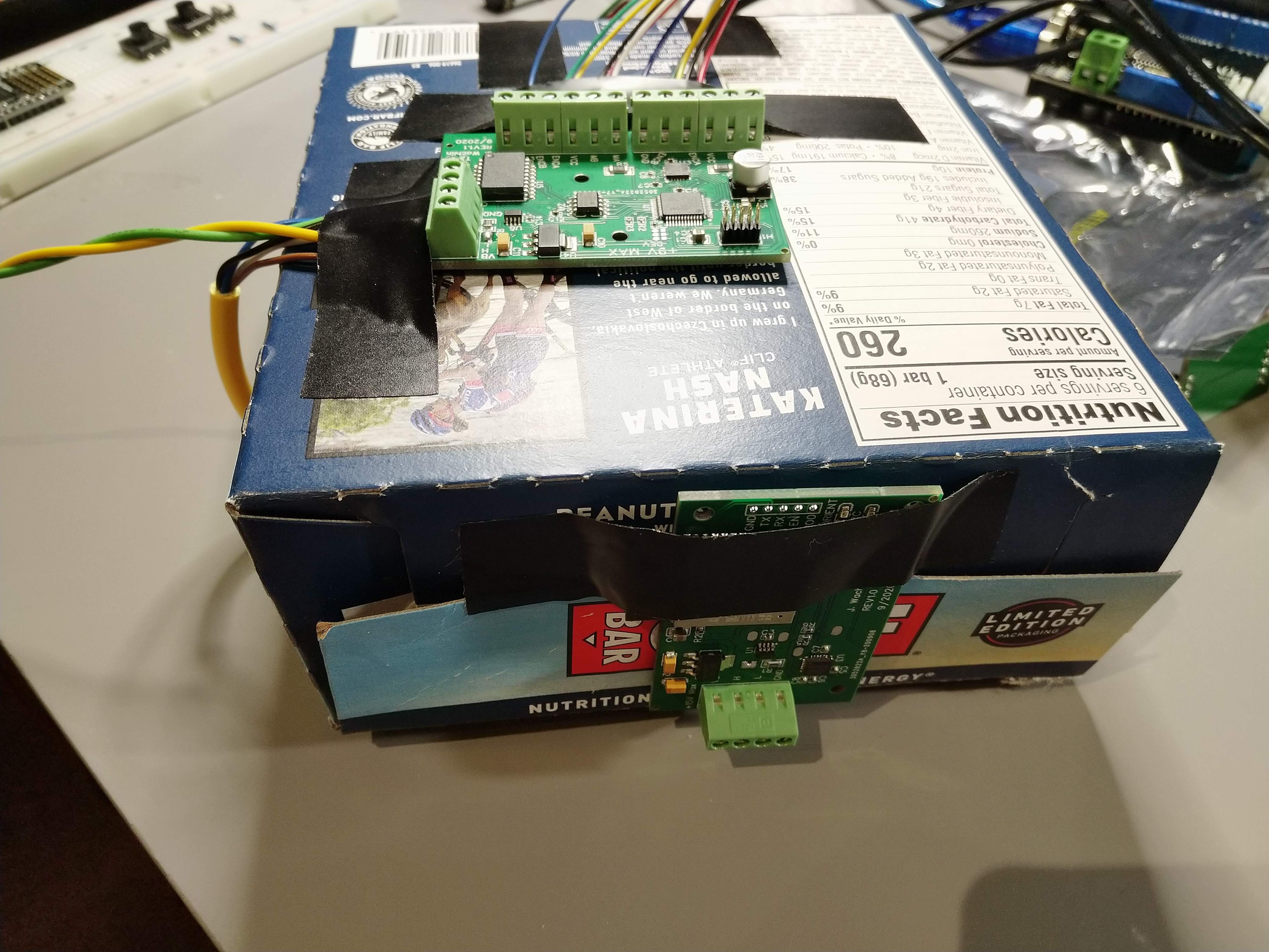
As an example of soft real-time interaction between the main controller and the dual motor controller board, I set up an "inverted pendulum" self-balancer using a Clif Bar box as the main structure. The main controller is taped to the top, and there is a proportional controller on roll (and, differentially, yaw) that commands open loop duty cycle commands to the motors. I had selected these motors for the high torque needed to drive the joints in a small walker robot, so they are not fast. The metal hubs used as wheels also get no traction on the desk and slip a lot.
The motors are mounted on a 3D printed frame I made in preparation for building a walking robot, which is then taped onto the box. Both PCBs are taped on as well, and a power tether runs to my power supply.
The peanut butter banana bars are the good ones.
What could possibly go wrong?
In the video, I clearly have to help it stay upright. With limited traction and slow motors, it is pretty limited. The hardware is clearly working though, which is what really matters here!
Next Steps
- Run system on a battery
- Control 2+ dual motor controllers from main controller
- Continue to add software support
- Motion primitives
- Time synchronization
- Position zero-ing command
- Further telemetry
- Improve CAN RX handling approach
- Speed control
- Build more demo projects
- SCARA arm/plotter
- Crawling robot
- Bipedal walking robot?
- Quadruped walking robot?
- RC drift car w/ torque vectoring and traction control (using faster motors)
Discussions
Become a Hackaday.io Member
Create an account to leave a comment. Already have an account? Log In.