 Raspibotics
MABEL (Multiple Axis Balancer Electronically Levelled)
MABEL is quite different from other balancing robots in that the legs are able to move and the robot does not need to run in a fixed position. This is where the Raspberry Pi and the servo controller come into play. I've written an Inverse Kinematics class in python that takes an (X, Y) coordinate and works backwards to calculate the angle of each individual robot joint required to move precisely to that position. Briefly, since we know the length of each leg section is constant, we can draw a virtual triangle using the X and Y component as the third line in the triangle and calculate the angles in the triangle using the cosine rule. Here upper refers to the distance between the upper leg pivot and lower leg pivot (92mm), lower refers to lower leg pivot to wheel centre (75mm), X and Y are given by the user (also in mm).
In code this looks like:
# IKSolve.py is an inverse kinematics module for MABEL to move the wheel (effector) in 2D Cartesian coordinates.
# Contributors: (@raspibotics)

# ***USAGE GUIDANCE***
# x translates the robot leg vertically and y translates the leg horizontally, each value should be in integer mm
# x is the distance between the upper leg pivot and wheel centre (Vertically) - acceptable range for MABEL (160-98mm)
# y is the distance between the upper leg pivot and wheel centre (Horizontally) - acceptable range for MABEL (-50, 50mm)

from math import acos, degrees, atan2


class IKSolve:  # IKSolve - Inverse Kinematics solver for MABEL

    def __init__(self, ru_home, rl_home, lu_home,  # IKSolve Constructor, Values are default leg section lengths in mm
                 ll_home, upper_leg=92, lower_leg=75):

        self.ru_home, self.rl_home = ru_home, rl_home  # Right leg servo home positions
        self.lu_home, self.ll_home = lu_home, ll_home  # Left leg servo home positions

        self.a_const_0 = (upper_leg ** 2) - (lower_leg ** 2)  # b^2 - a^2
        self.a_const_1 = 2 * upper_leg  # 2*b (c is unknown)

        self.b_const_0 = (upper_leg ** 2) + (lower_leg ** 2)  # b^2 + c^2
        self.b_const_1 = 2 * upper_leg * lower_leg  # 2bc

    def translate_xy(self, x, y, flip=False):  # translate_xy(x, y) Calculates the required angles to move to (x, y) mm
        if x == 0 and y == 0:  # (0, 0) resets servos to home position
            return self.ru_home, self.rl_home, self.lu_home, self.ll_home
        else:
            try:
                angle_a = degrees(acos(((self.a_const_0 + (x ** 2)) /  # A = Cos^-1((b^2+c^2-a^2)/2bc)
                                        (self.a_const_1 * x))))
                angle_a += degrees(atan2(y, x))  # Tan^-1(y/x)
                angle_b = 180 - degrees(acos((self.b_const_0 - (x ** 2 + y ** 2)) /  # A = Cos^-1((b^2+c^2-a^2)/2bc)
                                             self.b_const_1))
            except ValueError:
                print('Value specified is outside range of capable movement. Please specify a different value...')
                return
        if flip is not False:
            return (self.ru_home - round(angle_a)), (self.rl_home + round(angle_b)), (
                    self.lu_home + round(angle_a)), (self.ll_home - round(angle_b))
        else:
            return (self.ru_home + round(angle_a)), (self.rl_home - round(angle_b)), (
                    self.lu_home - round(angle_a)), (self.ll_home + round(angle_b))


IKSolve = IKSolve()

print(IKSolve.translate_xy(120, 40))
In practice this means the robot can be translated in all available Axes which allows MABEL to actively shift her centre of mass, lift up her legs to go over obstacles and keep the body level and lean into corners, all of which are impossible on a traditional rigid frame self-balancing robot.
On the Hardware side of things, MABEL uses a direct drive with gears and bearings which takes the load off of the servos in the weakest direction, eliminating wobbly servo shafts. This was a problem before, because of the cheap amazon servos I am using which allow the project to be more accessible.
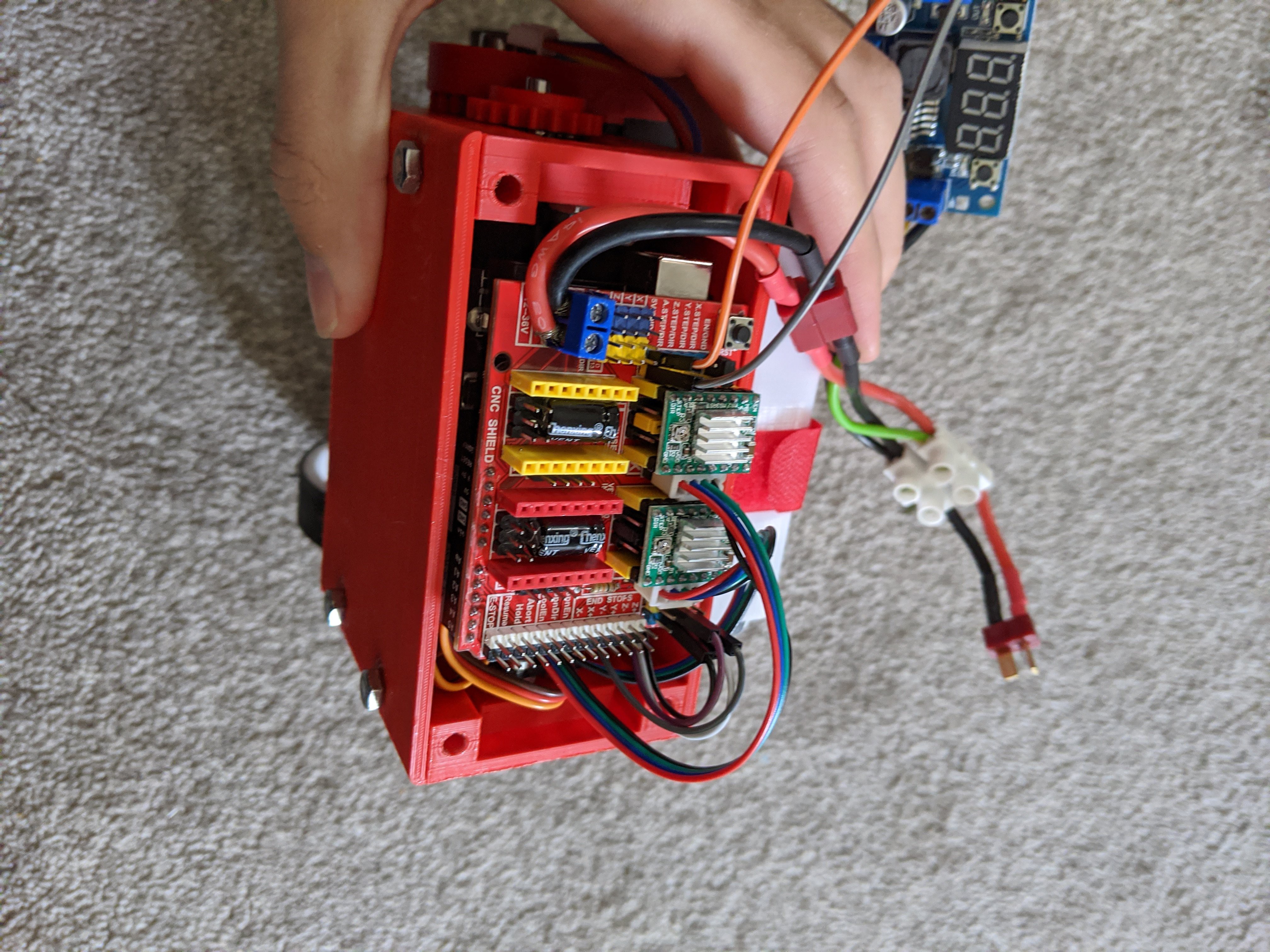
Like mentioned earlier, An Arduino CNC Shield + Arduino Uno stack is also used to handle of the real-time calculations and corrections that need to be processed faster than the raspberry pi on its own can handle. The CNC shield is particulary useful because it allows solderless assembly and has an I2c breakout for the MPU-6050 to plug nicely into, along with headers for the stepper motor cables.
The NEMA 17 Stepper motors that I've used are really commonly available and have all sorts of applications in 3D Printers, CNC machines, and now MABEL. The absolute positioning capabilities of stepper motors means that the robot can move directly, and precisely forwards and backwards without the need for closed loop control, like what would be required for a DC motor version. This allows for simple programming and ease of use with the already available YABR firmware which is able to control the stepper motors on 1/4 microstepping for added smoothness. The A4988 Drivers that I'm using also have current chopping which limits the current available to the stepper motors to protect them. My motors are 1.5A rated so I measure the voltage across the Vref variable resistor on the driver and set it to 0.96V - Initially it was set lower, but I found that just wasn't enough power to keep the robot going after it encounted an obstacle.
Now it can go over small obstacles with no problem, although it will be even better once the servos actively shift MABEL's legs to take the weight over the wheel that has the most load, keeping her body level and enabling more advanced terrain navigation.
Plans for the future...
- Simultaneous balancing and Leg height adjustment (soon)
- Dynamic cornering
- Arms (possibility, the mounting holes are already there)
- Video game controller remote control for ease of use (soon)
Contact me at raspibotics@gmail.com if you have any build questions or need instructions whilst documentation is still ongoing.