Close
0%
0%

Micro MUSIC

Angle of arrival 2.4GHz radio signal direction finding

Similar projects worth following
Angle of arrival (AoA) 2.4GHz radio signal direction finding using nRF52 series microprocessors. A simple beacon placed on a moving target (e.g. Model rocket, drone...), which can also transmit telemetry back to a a ground station with an antenna array allowing for AoA calculation using IQ data. Signal direction can then be used to drive some directional device (e.g. camera) or have multiple ground station to give absolution position.

This is a project I've been working on for a while, but finally decided to put it on here.


The basic idea is that Bluetooth 5.1 added AoA direction finding functionality, which several Nordic chip implement. This is done by measuring relative phase and amplitude (IQ) data from each antenna in an array receiving the same signal, or at least part of a continuous tone as only one can be measured at a time. This IQ data can then be used to calculate the angle(s) of arrival of the signal. Depending on the shape of the array different angles can be measured. For example a uniform linear array can only measure a single angle, from the axis the array progresses along. However, of full direction finding you need either a grid array or a circular array. For the purposes of this I will be using a circular array as it should be the most consistent from all directions.

The difficult part comes in calculating the angles from IQ data. I will mostly be looking at Multiple Signal Classification (MUSIC). This is actually more capable than what I need, as it can find the directions for multiple signals at the same time. However simplifying to only a single source signal removes some of the downsides to the algorithm, and is all this system will be capable of anyway. To summarise this algorithm a spectrum value can be calculated as a function of a test direction, this value should peak where the test direction matches the actual direction the signal comes from. Thus, we just need to find the peak in this function to get the AoA. However, even this isn't all that simple, as for a circular antenna, the spectrum value looks a bit like this:
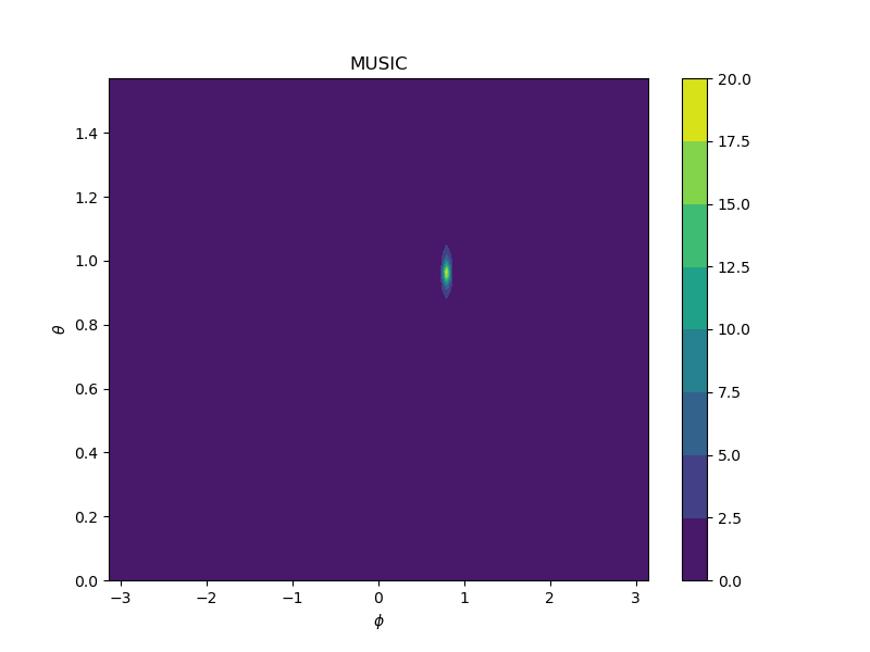
The issue being that the peak is very localised. While this is really good in terms of the uncertainty in the value, it is rather difficult to find quickly. We can't just measure all the values on a grid, as we would need to measure far to many of them, while things like gradient assent (gradient descent for the negative of our value) are also fairly slow as the gradient is practically flat for most of the region. I've found that an algorithm called COBYLA works quite well (and there is a version written in C which I can run on a microprocessor).

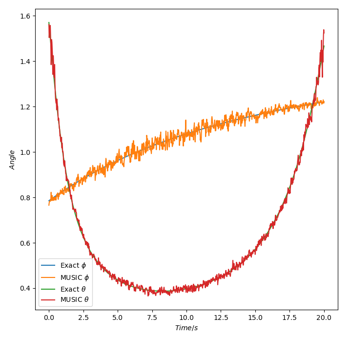
So now we are able to find the peak value, how well does this actually work. Well, for now we can simulate everything. As I'm planning on putting the source on a model rocket for camera tracking at some point, lets use that as an example. Just using simple projectile motion and a circular array of 8 antennas with radius 4cm we can get:
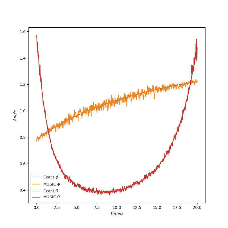
This also has 1% Gaussian noise in the "measured" phase as well as a simple low pass filter. It is likely this noise is far more than we will eventually get, but at this stage I don't know. Either way this looks really promising. For this we have used an update rate of 50Hz (ideally we want to measure at this or even faster). However, for the 20 seconds covered by this, it took roughly 25 seconds to calculate. Clearly this is a problem, but then this uses Python so really re should expect it to be rather slow.

The next step was to get MUSIC working in C/C++, for the time being this is still on my computer as its easier to test things. For this I set up a Unity project for some visuals and then used a native plugin for the C++ part. This has two parts, firstly I simulate the signal from a source points which can be moved around. Then I can render the spectrum plot on my graphics card, while also sending the simulated antenna data to the native plugin to calculate the AoA:
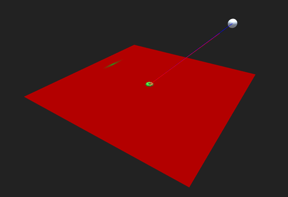
Here the blue line is the actual direction, while the red line is the calculated direction. This can already run in real time at about 50fps, and is also slower than we can get, due to passing data between Unity and the native plugin.

Finally we should get this running on a microprocessor. We can send the simulated IQ data to a MCU via serial. I have so far tested two different MCUs, firstly a Teensy 3.6 which takes about 10ms to calculate, and secondly...

Read more »

  • Just Keep Simulating

    Charlie Smith09/19/2020 at 18:02 0 comments

    In the previous log I finally managed to get IQ data, and with that the next set of problems. Firstly it seems that my data is very noisy and while I have made some improvements on that front, for this log I want to talk a bit more about simulations. I also promised to talk about running the MUSIC algorithm in real time on the nRF52833. However, that will also be in a later log, probably when I have direction finding working (so hopefully the next one but who knows).

    Firstly I would like to note that at the end of the previous log I suggested that one of the issues is that because the IQ data should have a frequency of 250kHz, then I should have been using this frequency in the MUSIC algorithm. This is wrong. At some point I found this page which eventual (look for a post near the end by robwasab) points out that a phase shift in the 250kHz baseband frequency will be equivalent to a phase shift at the 2.4GHz radio frequency. Thus, while the IQ data propagates at the lower frequency, the initial phase shift seen between sets of samples from each antenna is still based on the higher frequency. I think this is poorly explained by the documentation but it at least means we may not need a much larger array size to get AoA data. This also made me think about the what might be the best radius. I was initially thinking that I should probably have a larger radius anyway, but as we shall soon see from simulations, I may need to do the opposite and make the radius smaller.

    Simulated Signals

    For running simulations I am using a Python implementation of MUSIC. This not only performs the actual calculations, but also generates the simulated data from each antenna. This simulated signal is crucial to being able to make useful predictions from the simulations. If it is done wrong or poorly then I might as well not bother with simulations at all.

    To get a fairly accurate phase value we can consider a spherical wave from a source point R, traveling to each antenna at positions r_i. Then we can found the number of times the wave will cycle over the distance to get w_c. This will be some integer multiple of the wavelength plus an additional fraction to get a relative phase ψ_i. This phase isn't really relative to anything in particular, but can be made so by subtracting the phase from some reference point. As the phase of the data we measure is fairly arbitrary anyway this can probably be ignored.

    Using this, we can then add some amount of Gaussian white noise and we get a sample. To match what we can measure we can then make a number of samples by progressively offsetting the phase by 2π*250000*dt. Where dt is the time step between samples. I should note that each sample should have its own noise, rather than applying the same noise to all samples for each antenna. This should give a fairly accurate simulated signal base on the position of the source which we can vary over time. The only issue being that the noise being added is probably not really the noise that we actually see, but it will do for now. 

    We can also consider some examples for the typical motion we might see The first of these is some simple projectile motion based on an initial velocity and position. This is roughly what you might expect from throwing the beacon, or putting it on a model rocket (which was sort of the original aim of this project). This is the motion I have used for the simulated data shown previously. For the graph shown we use a radius of 45mm and a 1% phase error.

    Now let us consider a second test case. This is a bit more random, but is going to be sort of equivalent to running in circles around the receiver and waving the beacon around in the air.
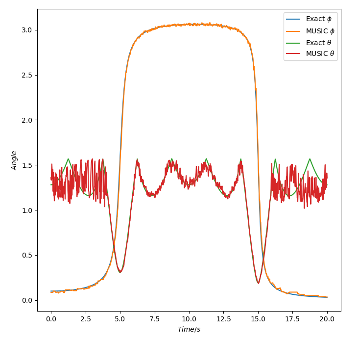
    So using the same settings as the previous run lets see what it looks like:
    Doesn't look too bad, but the start and end good do with some improvement. Well we where thinking of using a larger radius, so lets look at using r=100mm:Oh. Well that's quite a bit worse. So why could this have...
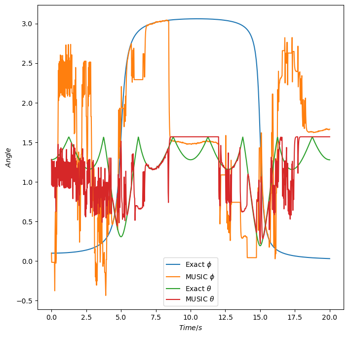
    Read more »

  • We have data

    Charlie Smith09/06/2020 at 01:07 0 comments

    The progress up to the end of the previous log is that I have two functioning radio boards and quite likely a functioning RF switch board. The next step being to actually measure in phase and quadrature (IQ) data. In the Nordic SDK, this is done by setting several registers on the radio peripheral to configure automatic constant tone extension (CTE) whenever a packet is sent, and then take IQ samples during the CTE of a packet being received. The IQ samples are then placed into memory to be processed with the MUSIC algorithm (or anything else).

    Transmitter

    So fist step is the code to transmit data. Most radio settings are the same as what are needed to transfer data normally. For now I don't actually care about the data being sent in each packet (but this could later be some sort of telemetry or similar). As such I can reuse my radio test code, based on the radio test from the Nordic SDK. I did modify this slightly to work with by board, as well as adding my USB logging backend. We then have to set two registers to enable CTE.  

    #define RADIO_DFEMODE RADIO_DFEMODE_DFEOPMODE_AoA
    #define RADIO_DFECTRL1_NUM_REPEATS 0
    #define RADIO_DFECTRL1_NUMBEROF8US (3 + (2 * (RADIO_DFECTRL1_NUM_REPEATS + 1)))
    #define RADIO_DFECTRL1 ((RADIO_DFECTRL1_NUMBEROF8US_Msk & (RADIO_DFECTRL1_NUMBEROF8US << RADIO_DFECTRL1_NUMBEROF8US_Pos))    \
                            | (RADIO_DFECTRL1_DFEINEXTENSION_CRC << RADIO_DFECTRL1_DFEINEXTENSION_Pos))                        
    
                        
    NRF_RADIO->DFEMODE = RADIO_DFEMODE;
    NRF_RADIO->DFECTRL1 = RADIO_DFECTRL1;
    Firstly DFEMODE, this tells the radio that  we are using angle of arrival (AoA). It can also be angle of departure (AoD) (but I've not experimented with that). I'm not entirely sure this register needs to be set, but it certainly works when set and in looking for how to do this I found this which suggests it should be. The second register DFECTRL1 is the more important one. It can be used to set a number of properties (which we will need to use for the receiver), but for the transmitter we just need to set the length of the CTE, and that the CTE should go after the CRC (so after the rest of the packet). The CTE length is given as a number of 8μs intervals. From the nRF52833 datasheet the sampling is given in the following form:So for 1μs slots for each of the 8 antennas, the total time should be 12μs plus 16μs for each repeat of the antennas (although there is probably no need for doing multiple repeats, using the longer sampling slots is more useful). The formula given then gives the number of intervals with a 12μs headroom to make sure all sampling finishes before the CTE ends (this headroom can probably be reduced with testing).
    Receiver

    The next step is setting up the receiver. This has several extra values to set. Firstly the RF switch control pins need to be setup. These will automatically be taken control of by the radio when needed (so shouldn't be used for anything other than the RF switch). The first step is to assign which pins are to be used. How many of these are set will depend on the array and RF switches being used, but can be any GPIO pins (I have seen some claims that they need to be high-drive only but this doesn't seem to be the case, at least not for my switching chips), do note that these should be set as outputs first using nrf_gpio_cfg_output.

    NRF_RADIO->PSEL.DFEGPIO[0] = PIN_A;
    NRF_RADIO->PSEL.DFEGPIO[1] = PIN_B;
    NRF_RADIO->PSEL.DFEGPIO[2] = PIN_C;

    Next the switching pattern needs to be set, this is done by clearing the pattern register, and then setting the default antenna to use, followed by the reference antenna and then each of the antennas to sample from. Generally the default and reference antenna will be the same, and then each antenna will be sampled in turn. If the RF switches being used switch too slowly (take longer than 2μs) you can add each antenna twice, then only use samples from every other slot. 

    // Clear the current pattern
    NRF_RADIO->CLEARPATTERN =...
    Read more »

  • Programming Time

    Charlie Smith08/26/2020 at 01:30 0 comments

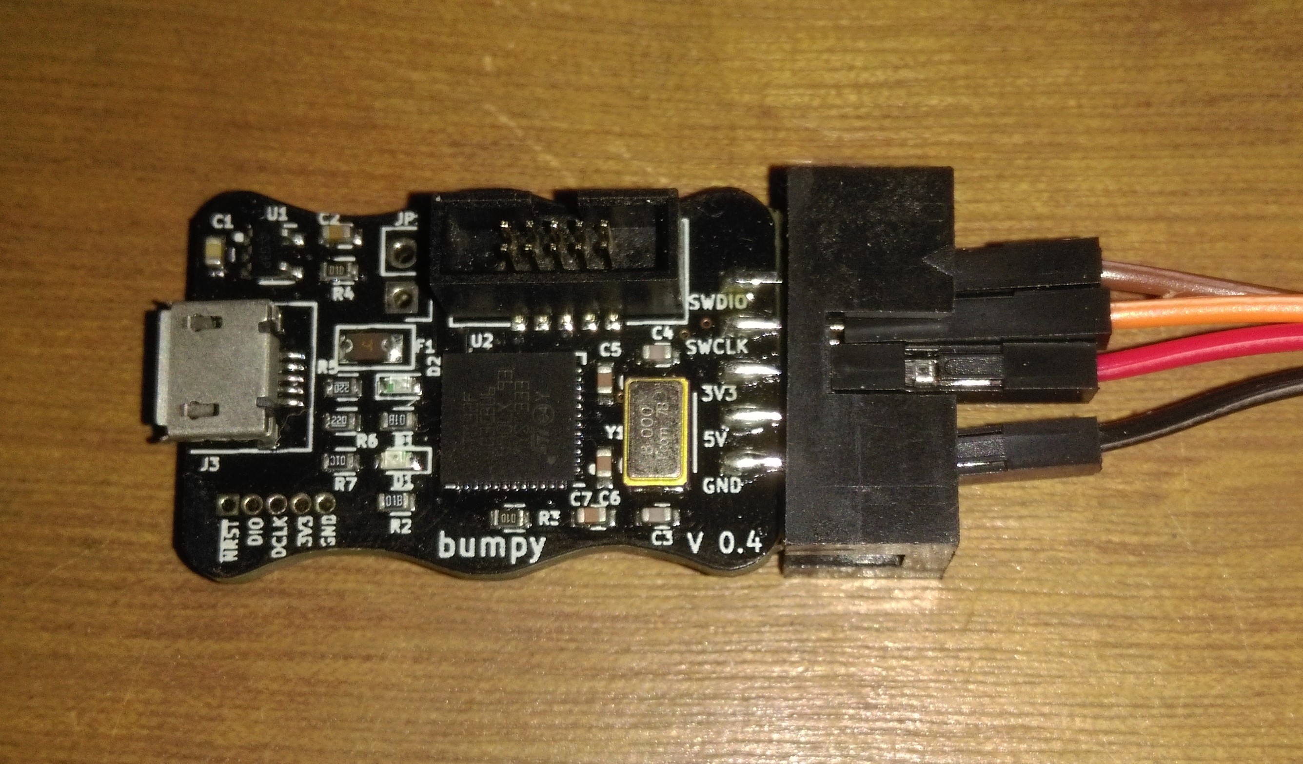
    In the previous log I build one of the radio boards and attempted to program it, running into difficulties about not having a programmer capable enough. I also mentioned about a new programmer called a Bumpy which has been designed to program nRF52 SoCs, specifically the nRF52832. As a reminder I'm using the nRF52833, a fairly similar chip, so it would seem that this programmer should work no problem. Well, as you may be able to guess, things are never quite that easy. The programmer firstly took quite a while to show up, coming from the US to the UK, but at least when I plugged it in everything seemed to be working. I would like to just include a picture of it here as I really like the look of the thing, I need to design more of my boards with interesting outlines:

    But this is where I ran into issues, as before I'm using Black magic firmware with GDB to program over SWD, previously only a generic Arm Cortex-M device showed up in GDB. With the new programmer, I still had this device, but also had one labelled as "Nordic nRF52 Access Port". With some playing around trying to use each of these devices, I still couldn't get something to program such that the "compare-sections" command would validate that the memory was correct.

    Eventually I discovered that this was down to the firmware of the Bumpy, and with some further digging through the source code discovered that in the nrf51.c file there is a method called "nrf51_probe". This gets called to check if a connected device is some valid Nordic MCU. However, in the Bumpy version of the firmware this is done by reading a device specific value from the MCUs memory to check against a list of known IDs to discover what the device is. Unfortunately, the nRF52833 is a fairly new chip, especially in the QFN40 package I am using. As such, the code for my chip is not in the list and so my board is not recognised as a Nordic device. While I was able to read this value from my chips memory, this isn't really the best solution to checking a particular device. One main reason why is that part of the check is so that the correct amount of memory can be assigned when setting up programming. However, the information for this is directly readable from the chip, so there is no need to use a reference table. What is more, the current up to date version of Black Magic does allow for any current and future Nordic SoCs to be programmed, buy checking if the device is in the nRF51 or nRF52 family before reading the memory sizes from the device. As I needed to reprogram the firmware on my Bumpy anyway, I thought it was probably best to use the more general form of the method in case I use any other chips. This was fairly simple, only having a slight issue of using dfu-util to update the firmware. From Linux the programmer wasn't recognised, while on Windows it claimed to successfully program it, but without actually programming it (which resulted in quite a lot of confusion as no change seemed to apply). Eventually I discovered I needed to use dfu-util with sudo permissions on Linux for the programmer to show up, and then everything just worked.

    Toolchain
    So having waited a month for the programmer to show up and probably another week just being able to use it I can finally get started. Well yes and no, before starting this project, I had only ever programmed things via the Arduino IDE. So it was quite a leap to be able to even set up the toolchain. This wasn't helped by wanting to do everything on Windows (as I only have Linux installed on a laptop and don't want to use that for everything). I found something called MinGW installed make, GDB and the compilers I need grabbed a copy of the Nordic SDK and managed to get everything set up. While I didn't really know how to use make files (and still don't fully), Nordic provided some really good templates and with only some small changes so I could setup project directories in a way I like I was able to compile a program. While I had been able to do this before...

    Read more »

  • Radio Board Assembly

    Charlie Smith08/06/2020 at 12:41 0 comments

    After waiting a few weeks, the PCBs are now in my possession. I also have all the components I need to build them, even with some self sabotage by ordering the wrong antennas and forgetting to order a coax cable with the parts for Digikey. Firstly we have the radio board:

    And secondly the antenna board:

    Initial inspection shows everything to be in order. I should have tented the bottom side of the thermal vias on the antenna board, but its not really a problem. I also should have a bit more imagination when it comes to silkscreens but that doesn't affect anything electrical.
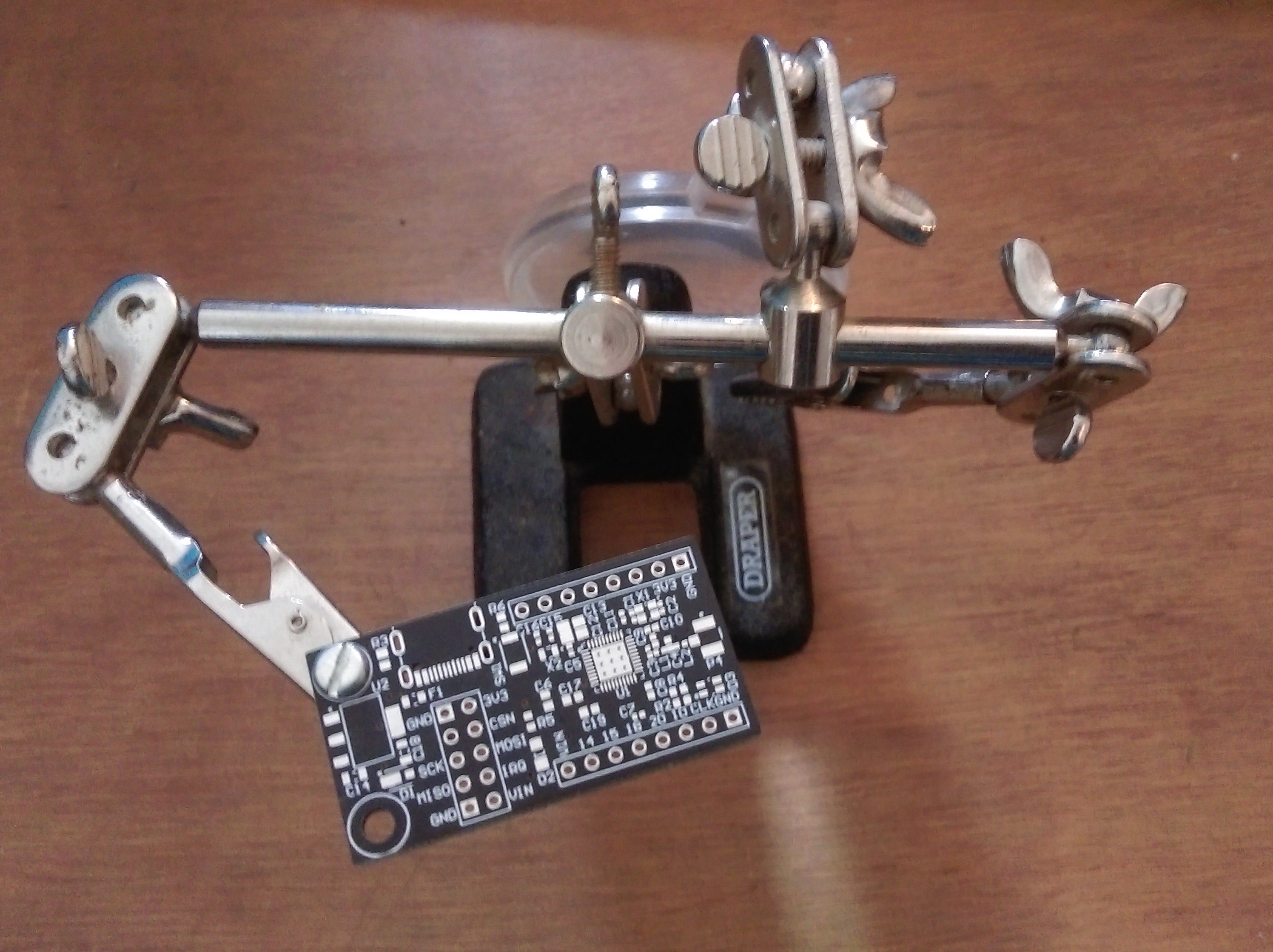
    I am very happy with the rounded corners on the PCBs, possibly I should have used a larger radius, but I think all my projects will use rounded corners from this points. Also I would highly recommend having mounding holes all over the place. It the board to be held much more easily, and without the possibility for damage to the board from what is being used to hold it. All you need is to put a bolt through a hole, attack it in place with a nut on the other side and then have something hold the bolt:
    For larger boards you might want to do the same thing at the other end of the board to help support it, but even with just one, it is fairly stable.
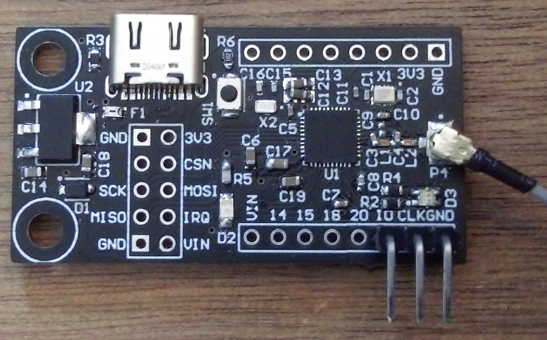
    Next is soldering everything on. I will gloss over this as there are plenty of guides on SMD soldering, and as I'm using neither a stencil or re-flow oven, I'm hardly a good influence. The main points of interest are that I'm glad I changed away from 0201 components that the Nordic design suggested, the USB was much easier to solder than the normal USB-C connectors, and that when soldering QFNs like this it is a good idea to re-flow the solder paste before butting the chip on to make sure there is enough on all the pads. An afternoon later gives me:

    Not the neatest ever, and it could do with cleaning some of the flux off, but not the worst job ever. Now I just need to program it right. Well this is where I've run into problems. I got a couple of ST-LINK clones and put Black Magic firmware on one. However, after several days of banging my head against a wall, I discovered that while the Black Magic firmware does support nRF52 chips, only the latest version does. What is more, the latest version needs more flash than these cheap programmers have. As such I need to find a new programmer. The option I went for is a Bumpy, which is more or less one of my cheap programmers with enough memory for the up to date firmware. However, this will take a while to arrive so will leave this for now.
    As an extra note, a thought came to me (just a few days before the new programmer should arrive) that I could probably just replace the chip on one of my cheap programmers with one with enough memory, and use the other programmer to program the correct firmware on it. Unfortunately I have already ordered the better programmer (and this might not actually work), but its something to try out whenever I next order components.

  • PCB Design

    Charlie Smith08/06/2020 at 12:07 0 comments

    With everything simulated we now need to build it. I've decided to use one of the Nordic nRF52 MCUs. There are several which can implement direction finding: nRF52811, nRF52820 and the nRF52833. These all have a 64MHz Arm Cortex M4. However the nRF52833 has an FPU, while the nRF52811 doesn't have hardware USB. There are clearly other differences, such as memory, but these are the main ones. So far we have tested MUSIC on a Teensy 3.6 and 4.1, the 3.6 also has an Arm Cortex M4 with FPU, so the nRF52833 is likely needed, purely for performance reasons. Although we can always collect the data on the nRF and send it to a more powerful MCU such as a Teensy 4.1. I originally designed this for the nRF52820 as I thought it was more available, and is pin compatible with the nRF52833 so I can always upgrade it. However in the end I was unable to get either the nRF52820 or nRF52833 from normal component distributors, but was eventually able to get some nRF52833s directly from Nordic.

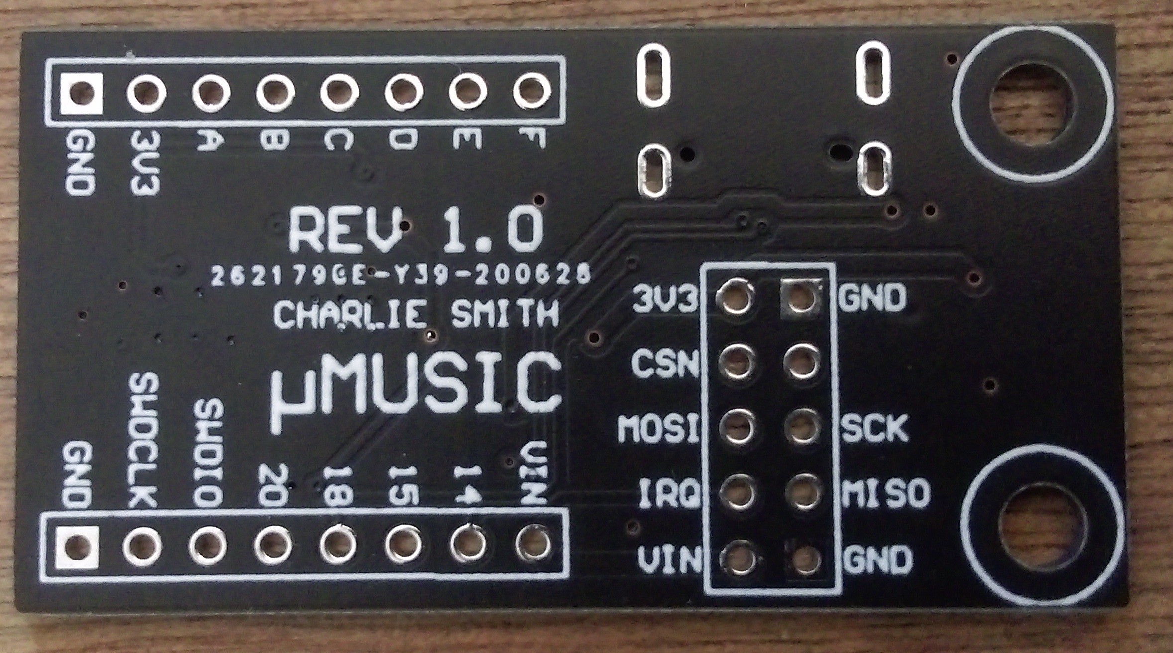
    So I can use the nRF52833 for the receiver, but as much as I would like to use a pre-made nRF24L01+ for the transmitter, I unfortunately can't as the transmitter needs to be able to enable a continuous tine extension (CTE) at the end of each data packet. However, all this means is that I should design a single transmitter/receiver to be used at each side, and then allow for changing the antenna on the receiver to go to the antenna array. For this array to work, the MCU needs to switch between each antenna, so I also need to break out some GPIO, and while I'm at it I will break out all of it so the board can be used for any future projects:

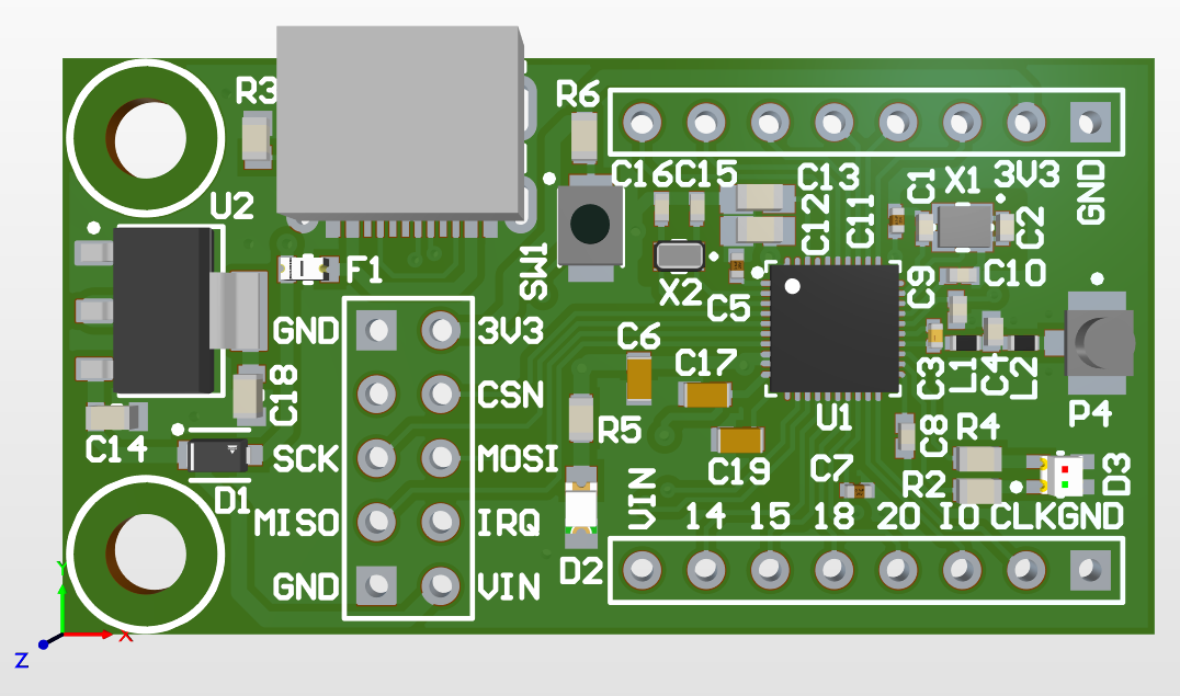
    This is a fairly simple design (it looks quite complicated as I labelled everything) but really it just implements a standard design from Nordic, while also having a complete overkill of a LM1117-3V3 regulator as I want it to run at 3.3V to make interfacing with anything else easier. I also added a bi-colour LED, reset switch and USB connector. For the USB, a friend keeps pestering me to use USB-C so I did, although I cheated slightly by using a USB 2.0 only one which has a single row of connectors making routing and soldering it a lot easier (Its a DX07S016JA1R1500 if anyone else wants to use it). I'm also using a U.FL connector for the antenna as they are much cheaper than SMA and you can get very cheap U.FL dipole antennas from eBay.

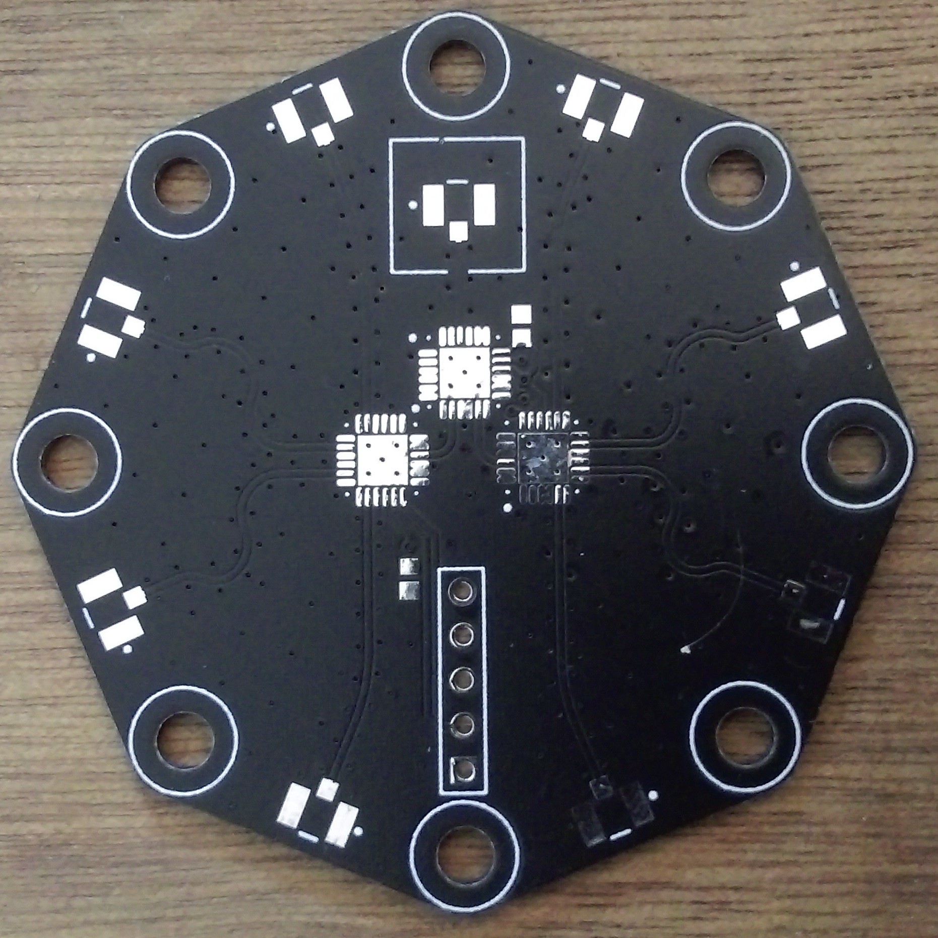
    We also need a second PCB for the antenna array. For now I'm planning on using an 8 antenna circular array. As such I need to be able to switch between each of these antennas. Looking at the datasheet for the nRF52833 we find this:
    We get a 1μs or 2μs switch slot, so ideally we need to be able to switch faster than this. This isn't a huge requirement, as we can continue switching during one sample slot, but then ignore the sample giving up to 6μs switching time. Of course this does make the entire operation take longer so isn't idea. One option for the RF switch is the HMC253AQS24E. This is SP8T so can switch 8 antennas all in a single chip, and has a switching speed in the tens of nanoseconds. However it is rather expensive and can't be used if we wanted to increase the number of antennas at a later date. An alternative option is a number of SP4T chips such as the PE42442. Of course we need 3 of these to get 8 antennas, but if at a later date I wanted to, I can use 4 of them to get 12 antennas, or 5 for 16 antennas. This PCB seems much simple, but is by far the most difficult one I've had to do so far:
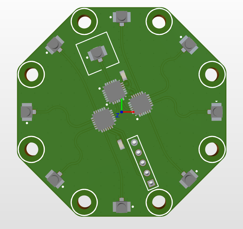
    The main problem with this board is that everything needs to be inductance and length matched to allow for ideal operation. I also ended up using a 4 layer PCB so that when the PCBs are made by JLCPCB I can get a controlled impedance PCB (and they put the price down shortly before I ordered these which was nice). This board was also a pain as everything is at an angle, which did result in me finally learning how to use grids in Altium (which is going to be really...
    Read more »

View all 5 project logs

Enjoy this project?

Share

Discussions

k.ninja13 wrote 02/22/2023 at 19:39 point

Did you run into a roadblock on this project after getting the hardware together? I'm looking at doing something similar for bluetooth tracking myself and liked reading the posts so far!

  Are you sure? yes | no

Similar Projects

Does this project spark your interest?

Become a member to follow this project and never miss any updates