This project has been was sort of put on hold again shortly after the last log. While at the time I had made significant progress to getting it working (it could run most unconditional instructions), it promptly stopped working again. I also had only been working on it while I was unable to work on another project as I was waiting on something to arrive, so when I could continue with that this was put back on hold. However, as I decided to take a short break with that other project I decided to have another look at this one.
Additionally thank you for the comments, and sorry for not replying till now. Firstly for the clock I will probably use a Schmitt trigger to buffer the signal, but currently I don't have any so will stick to the 555 timer which does the job for now. Secondly, I'm not sure if there is a race condition, control bits should be set out of phase with the clock being active. But even after the fixes I will talk about shortly, I very much still need to use capacitors on the control lines to slow the signals down. Possibly the GLS29EE010 EEPROMS can't drive chips that far away in addition to an LED, and need a buffered output (dimming the LED may also help, and probably should be done anyway). For all data LEDs in modules, they are actually buffered using 74LS245 octal bus transceivers, so while it probably doesn't affect the ability for data to be moved around, it does result in quite a large current draw (especially when lots of modules have data). Finally, yes simple probably isn't the best term to use. But in comparison with even fairly simple microcontrollers or existing CPUs, it is relatively simple. At the very least I can built it and not worry too much about some aspects of the design.
So lets start looking at some of the problems the computer had. The first issue was that the output control bits for the current instruction register (CIR) where done incorrectly. This is mostly due to some unnecessary complication I added to allow for some extra functionality which is probably not going to be used. The CIR is a two word register where the 6 least significant bits give the OPCODE of the current instruction, while the remaining 26 bits give the OPERAND. This is needed because with only a single word, only a 10 bit OPERAND would be available and so only 1K words over RAM. Because I wanted the full 64K words available I need to allow instructions to make use of two words when the OPERAND is a memory address. This mean I need to be able to output a 16 bit value to the bus. However, if the OPERAND is a number less than 1024, then only a single word is needed and I only need to output a 10 bit value to the bus. Finally the overcomplication: With 26 bits of OPERAND available, I can allow for instructions to use two 13 bit arguments as an OPERAND. This lets me make full use of the two word CIR, but does mean that I need to allow for two 13 bit values to be outputted to the bus, one offset by an additional 13 bits. This gives 4 total output modes:
- FAST: The last 10 bits, from the first word
- FULL: The last 10 bits from the first word and the fist 6 bits from the second word
- MLT_0: The last 10 bits from the first word and the first 3 bits from the second word
- MLT_1: The last 13 bits from the second word
However, having multiple arguments isn't all that helpful (especially with a quite limiting 6 bit OPCODE, I should have made it 8 bits). The issue is that somewhere along the line the control logic for getting these different outputs got messed up. Firstly the FAST, FULL and MLT_0 control bits where being inverted, and secondly they where not being combined correctly anyway. Luckily, I could correct the problem quite easily by replacing an 74LS32 quad OR gate with a 74LS02 quad NOR gate, and redoing a few traces:
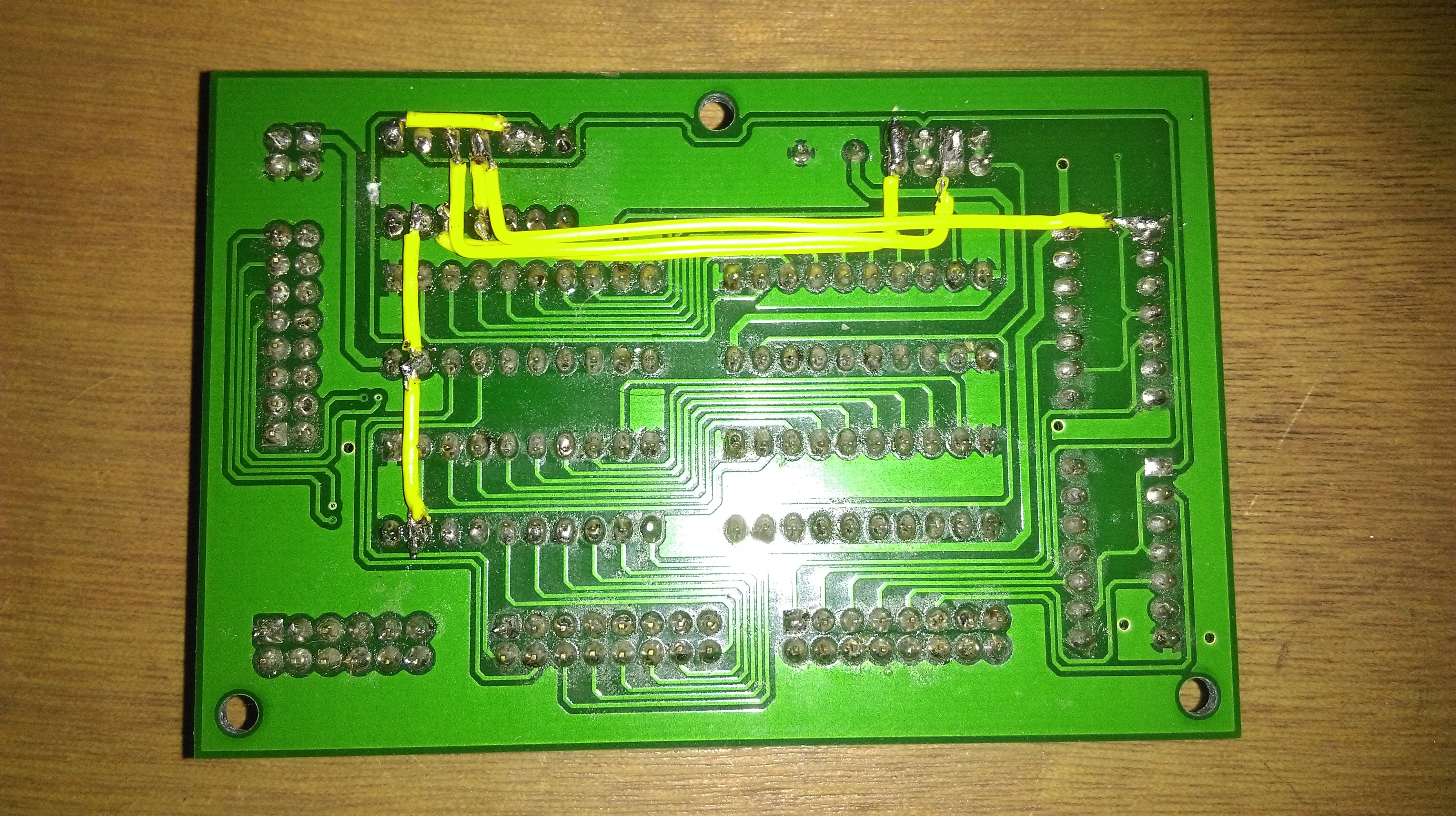
I also needed to un-invert the control bits. This is also quite easy, as each control word allows contains not only a GLS29EE010 EEPROM, but also a 74LS04 hex inverter. This doesn't allow for all control bits to be inverted, but as this is not needed for most bits this isn't a problem. To allow each control byte to be identical in hardware, each byte gives an inverted and non-inverted version of each bit, and so the connection can be easily swapped.
The next issue wasn't really that important, but it annoyed me enough for me to fix it. The issue was that because I made the first 32 words of RAM to be given in EEPROM, I needed to make sure that the RAM ICs and EEPROM ICs didn't try to output a value at the same time. However I always need one of them to output to make sure that the LEDs would show the value at the address given by the memory address register (MAR). What's more the RAM ICs being used (AS6C1008-55PCN) only have one data connection, meaning that the same pins are used for the data when reading and writing, making the control logic even more complicated. The result of all this added complexity is that I messed up a tiny bit and so the LEDs would only be lit if the RAM is currently reading or writing data, but not if neither operation was being performed. As I said this doesn't affect the functionality of the computer, but It does affect the lots of LEDs condition so needed fixing. Luckily it was an even easier fix than the last one, requiring only a few traces to be swapped around:
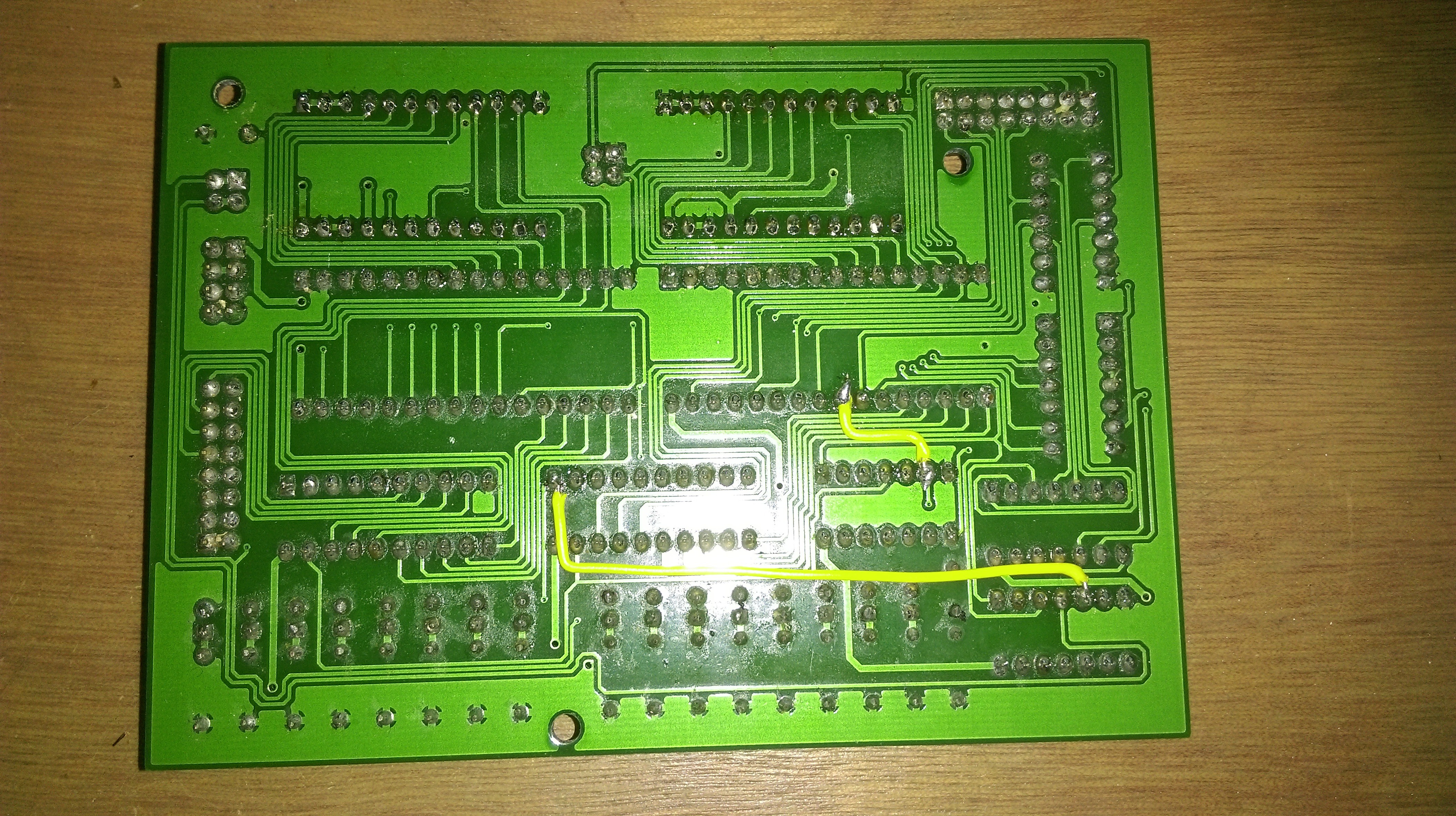
The previous problems where actually fixed around the time of the last log. However, even with these fixes, the full computer still didn't work. As a hopefully easier problem to solve, I decided to look at why one of my GLS29EE010 EEPROMS was always outputting high on all bits. This was actually on an unused control byte, but it still was something that needed fixing. The strange thing about this issue, was that my EEPROM programmer seemed to be able to write data to the EEPROM, and also read it back correctly. And yet the data would always seem to be high. Now, it is important to note that the programmer I'm using is designed by me, and so not immune to problems (in fact it has had quite a few since I built it). So to test where the problem is, I setup the EEPROM in a breadboard such that I could change the address and see what value was stored. This promptly showed that the programmer was correctly reporting that the data was all 0xFF (all bits high) where I had been looking. However, only in the first half of ROM. The second half had the data I had been expecting to be in the first half. This quite clearly points out the issue. The GLS29EE010 EEPROMS have 128KB of data, and so 17 address lines. However, in my programmer I use two 74HC595 8 bit shift registers to output the desired address from an Arduino Nano. To allow for programming all data, the final 17 address line is given directly. In this case the pin A5, typically an analogue pin on the Nano, but can also be used as a digital pin. However, in my code I accidentally used:
#define ADDRESS_16 5
Rather than:
#define ADDRESS_16 A5
So the address line was never being set, and so it seems was always being treated as high and so any data was being written to the wrong half of ROM.
This actually fixed quite a bit more than what I thought it would. At some point I also found a problem with the microcode of some instructions. While this had been fixed (or so I thought), and the EEPROMs reprogrammed. Due to the programmer having this issue, I had never applied the change.
The final fix is unfortunately not quite so described (and a problem I was rather dreading). With such a large project, it is quite likely that there are some poor solder joints somewhere. The problem with this, is that there are quite a lot of places this could be. Additionally, the joints will typically pass a continuity test most of the time. I really didn't want to check every solder joint everywhere, however I luckily had some hints that the problem was around the control logic. While I'm still not entirely happy that there aren't similar issues elsewhere, I did find a few places that definitely needed re-soldering (and removing some fluff), and low and behold:
It actually works! The test program shown counts from 0 to 120 in multiples of 3, then resets. This is quite a good test as it makes used of addition, subtraction in the ALU; the A, B and OUT registers; as well as conditional and unconditional jumps. There are still a few parts that need to be tested, but we will get to that
So the computer works. This is quite good for my motivation so hopefully I will able to do some more with it shortly. There are still a few parts that aren't quite finished:
Clock
This is currently on a breadboard. Clearly not something allowed by my rules. It would sill be nice to use the original clock, but as mentioned at the start, I will need to look into using Schmitt triggers to buffer the signal. I may also look into having a high frequency mode using a crystal of some sort. However, I'm not really sure what the maximum frequency I can get with the computer. I think there is an absolute maximum of about 4MHz, due to the switching characteristics of the chips being used. But as I approach this frequency, I will also need to be careful about propagation delay to make sure signals don't arrive in the wrong order.
Program Memory
This is one of the main changes (other than using a 16 bit word obviously). While currently untested, I see no reason as to why these shouldn't work. Most of the hardware is duplicated from other parts, which seem to already work. However, my EEPROM programmer has had yet more problems. To store the program, I am using what I will refer to as a program card or program cartridge:
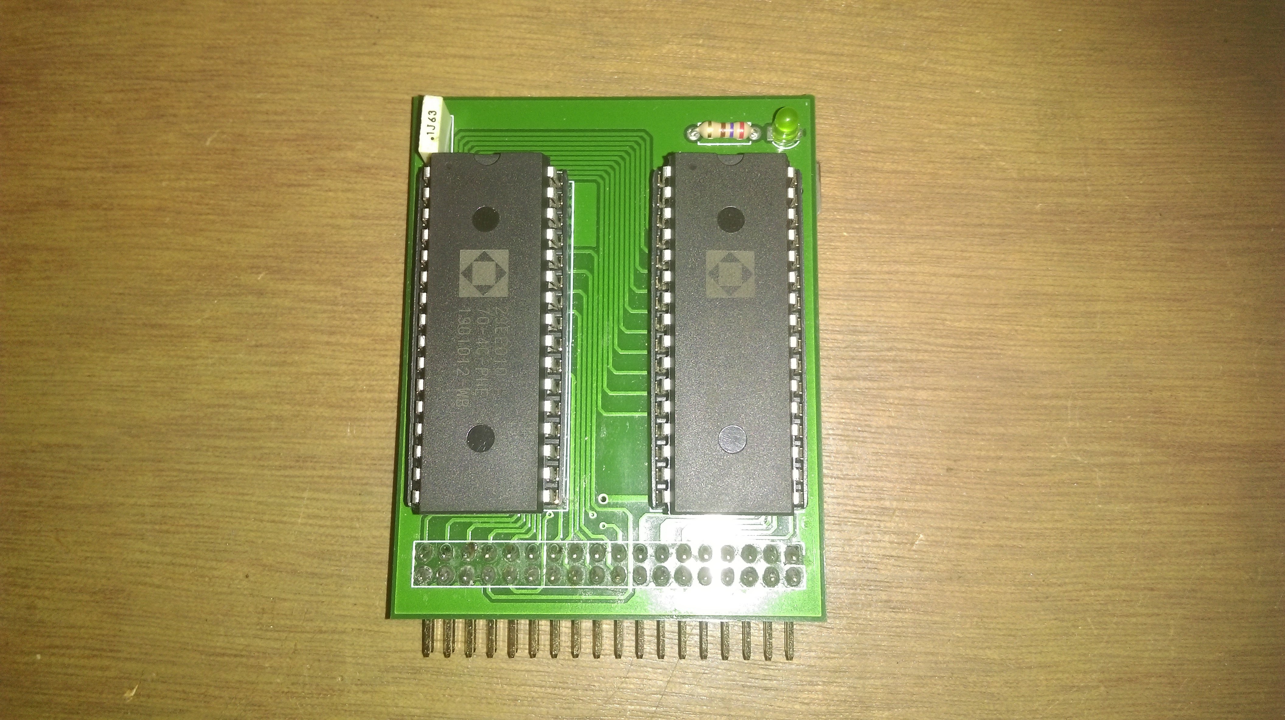
This consists of two GLS29EE010 EEPROMs, to make up a 16 bit word. Now in the design for this I have included the write and read enable controls in the connector. This means I can just plug this into my programmer board, and program both chips without removing them from their sockets (which risks damaging them). However, my programmer can only output a single byte at a time. Now if we look at the schematic of the program card:
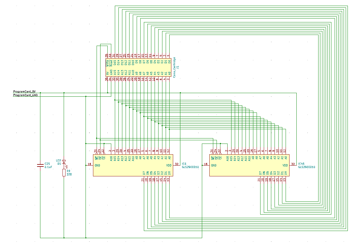
If we consider what will happen during a write process it will quickly become apparent that when we write to one EEPROM, the other will also be in a write mode. But because we are only supplying the data to one of them, the other will have floating inputs. Due to how you program these chips, it probably wouldn't mess up the data, as it will never enter a programming state. But it is still best not write single bytes in this way. Rather than design a whole new programmer, I can split the write enable signals. As of writing this, I can only write one byte this way. But hopefully this will be solved shortly.
Input Register
This would be quite nice to get working. It probably doesn't need much work, but as it isn't all that important I haven't got round to it yet.
C Style Compiler
As this computer is off my own design, there isn't and normal compiler which supports it. I have actually already got an assembler which can be used to one to one convert instructions to the machine code needed to be put in memory. This also handles placing variables into RAM, along with allowing for blocks of code to eventually form functions. On that note, the computer does support functions, however there is no hardware module for a stack pointer. As such, implementing adding and removing items to and from the stack is quite slow (not that anything here is particularly fast anyway). However, implementing this sort of thing is quite a lot of hard work, really we want something to do that for us (and yes that means I'm using my computer with a GHz clock speed to program something that is currently less than 1KHz, but I would rather not spend all my time manually generating machine code).
Let us consider the test program shown previously. This counts from 0 to 120 in increments of 3 and then resets, so lets look at the assembly code:
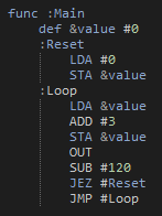
What we really want is to define something like this (and yes I know its note quite the same as the condition is in a different place):
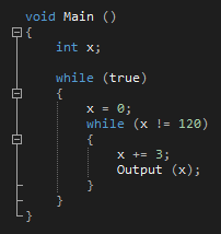
Now this looks about the same amount of code. But this is also a very simple case. If we where to start doing anything even slightly more complex (imagine multiplying two numbers when all you can do is add and subtract), it will become far cleaner to use this C style code. However, this is going to be quite a lot of work, so don't expect anything too soon.
So there we go, the computer works for the most part. There are still a few things to sort out, but hopefully I won't run into my previous problem of not seeing any clear way to progress as I did before. I also would like to share one of my personal beliefs about this sort of thing. Every problem as a certain amount of time which you need to spend to solve it, the only reason you have yet to solve it is that you haven't spend the time working on it. Now maybe this isn't very good advice, but it helps me come back to something that has been left for a while, just in case I only needed a little more time to get it working. Although, it also seems that sometimes the best thing to do is leave a project for a short time. It can also be quite common that I suddenly have an idea about a solution to something even when not currently working on it.
Anyway, that will do for now. As usual, feel free to ask any questions. Hopefully I will get round to answering them slightly sooner this time.
 Charlie Smith
Discussions
Become a Hackaday.io Member
Create an account to leave a comment. Already have an account? Log In.